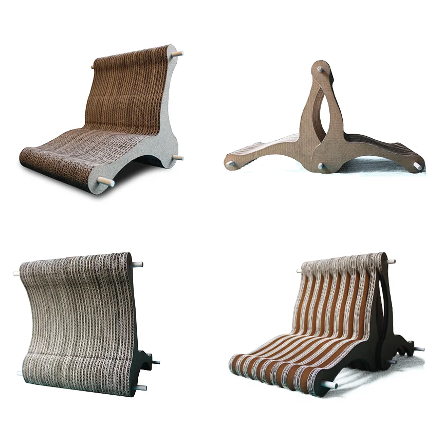
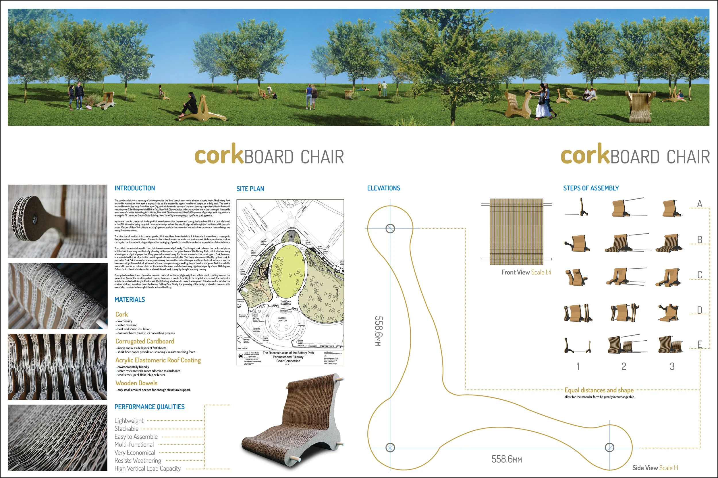
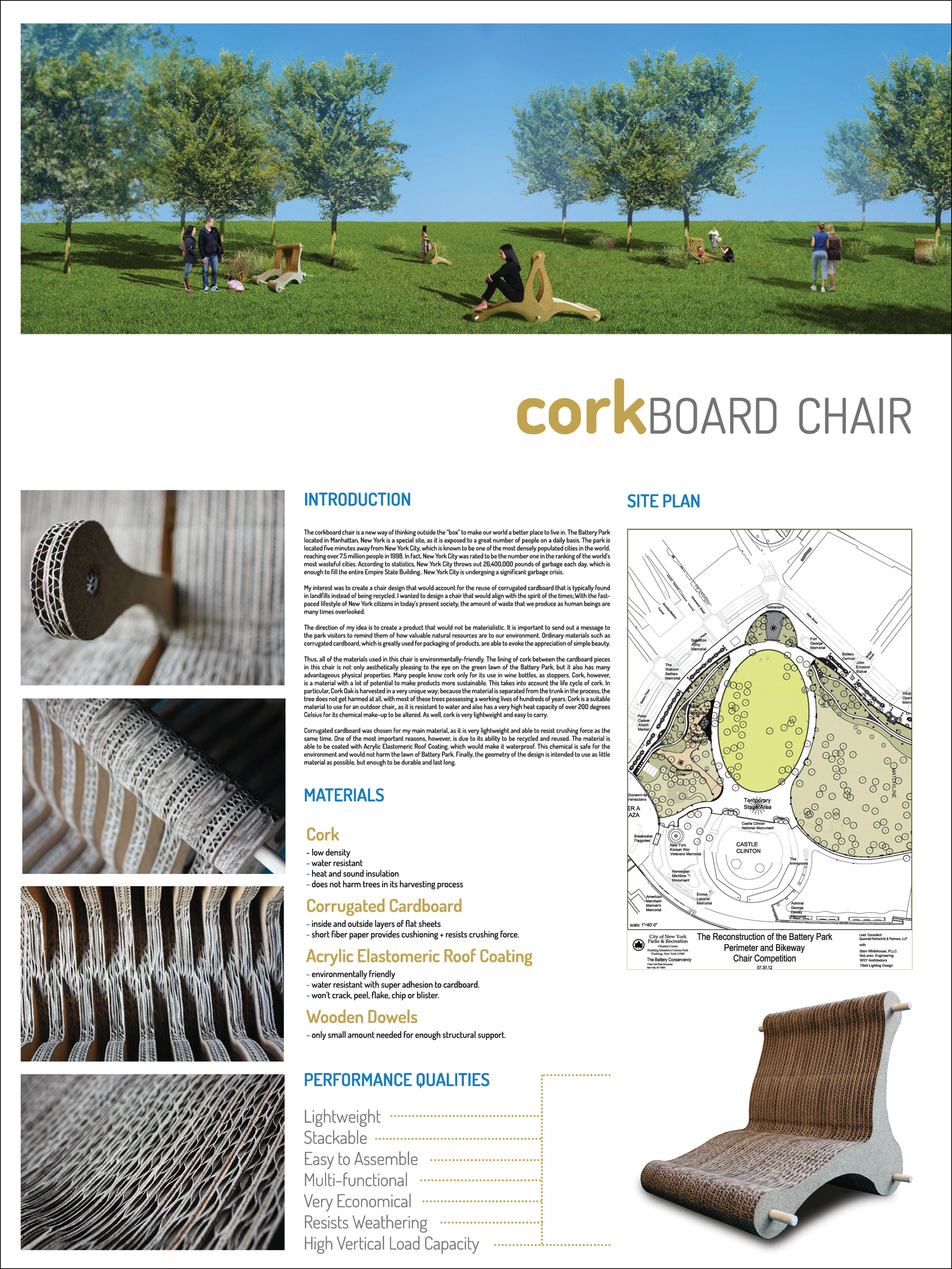
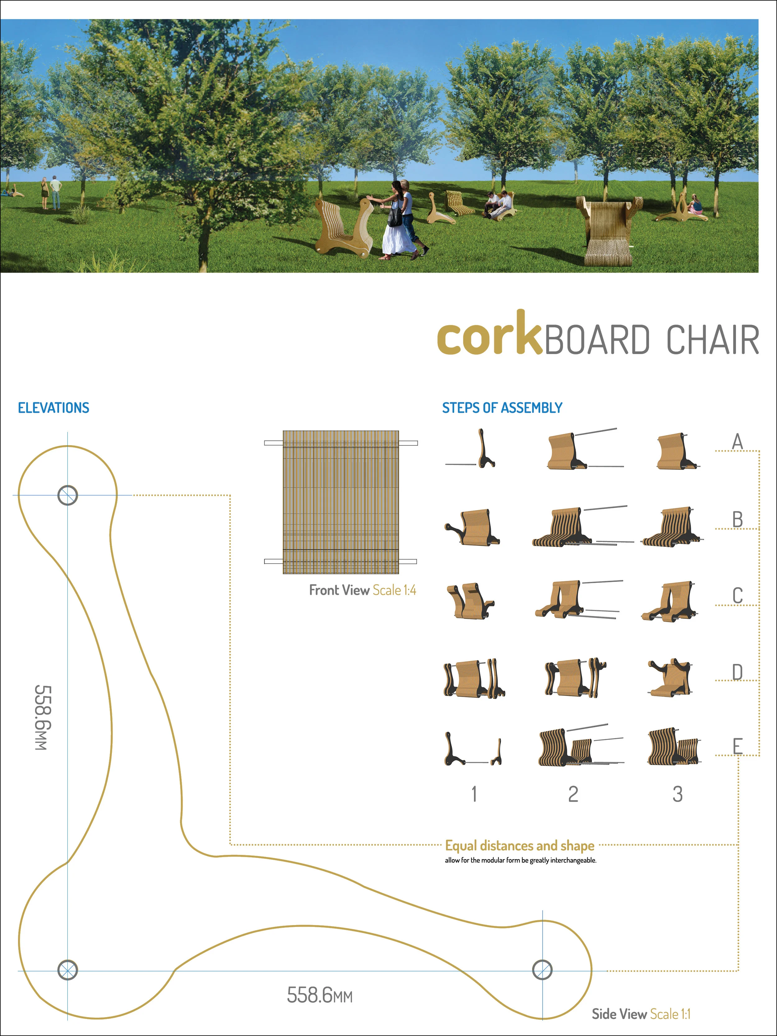
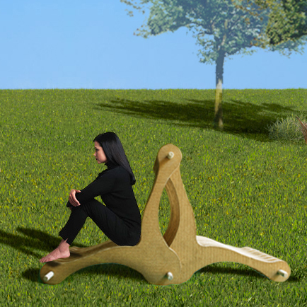
The Corkboard Chair is a new way of thinking outside the “box” to make our world a better place to live in. The Battery Park located in Manhattan, New York was a special site, as it was exposed to a great number of people on a daily basis. The park was located five minutes away from New York City, which was known to be one of the most densely populated cities in the world—reaching over 7.5 million people back in 1998. In fact, New York City was rated to be number one in the ranking of the world’s most wasteful cities. According to statistics, New York City throws out 26,400,000 pounds each day, which is enough to fill the entire Empire State. New York City was undergoing a significant garbage crisis.
My goal was to create a chair design that would repurpose corrugated cardboard, which oftentimes ended up in landfills. I aimed to design a chair in line with the spirit of the times: given the fast-paced lifestyle of New York citizens in today's society, the amount of waste produced as human beings is often overlooked. My creative direction was to create a product that would not be materialistic. It was important to send a message out to the park visitors to remind them of how valuable natural resources are to our environment. Ordinary materials such as corrugated cardboard—greatly used for the packaging of products—had the ability to evoke an appreciation of simple beauty.
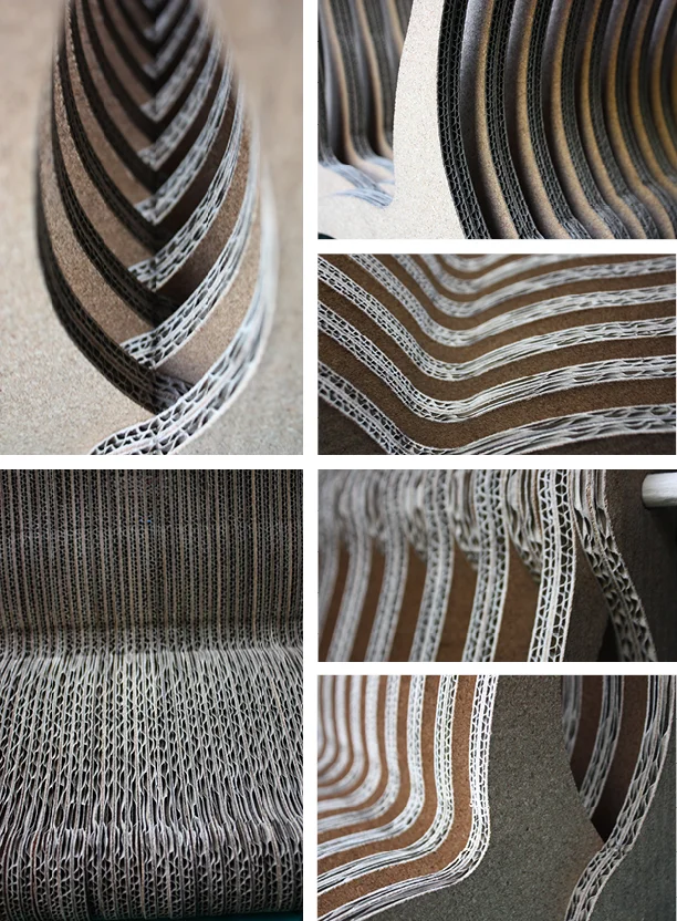
Thus, all materials used in this chair were environmentally-friendly. The lining of cork between the cardboard pieces not only looked aesthetically pleasing against the green lawn of Battery Park, but it also possessed many advantageous physical properties.
Many people recognize cork solely from its use in wine bottles (as stoppers) or on the surface of bulletin boards. However, cork is a material with significant potential for making products more sustainable when considering its life cycle. I discovered that Cork Oak is harvested in a unique way: the tree remains unharmed because the material is separated from the trunk during the process. As a result, many of these trees have working lifespans spanning hundreds of years. Cork is an ideal material for an outdoor chair, as it is water-resistant and requires temperatures over 200°C to alter its chemical makeup. Furthermore, cork's low-density properties make it lightweight and easy to carry. It also excels in insulating both heat and sound.
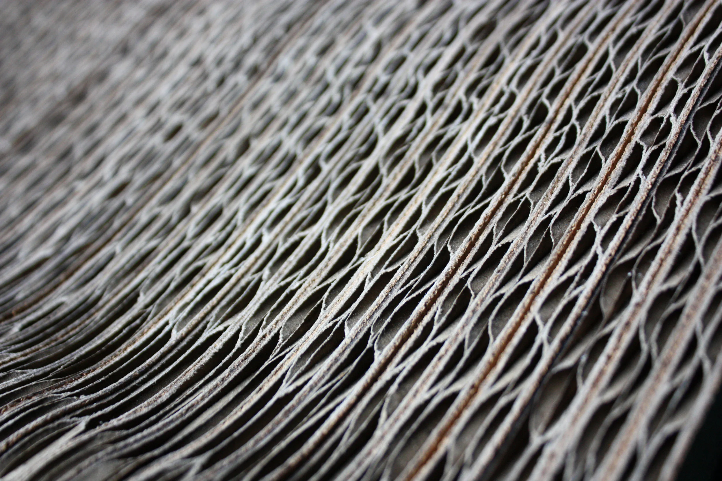
Corrugated cardboard was chosen as the main material because its short fiber paper is not only lightweight but also has the ability to resist crushing force. One of the most compelling reasons for its selection, however, is its recyclability and reusability. The material can be made waterproof when treated with Acrylic Elastomeric Roof Coating. This chemical is environmentally friendly and would not harm the lawn of Battery Park. In addition to its water-resistant properties, the coating offers protection against cracking, peeling, flaking, chipping, and blistering. 3 to 5 wooden dowels were required for structural support.
The design of the single module’s geometry was to use as little material as possible without compromising its strength, durability and sustainability. I went through several design iterations in order to fully optimize the Corkboard Chair's performance. One of the main design objectives was to find an ideal shape for the single module, as I wanted it to be easy to assemble, multi-functional, and have a high vertical load capacity.
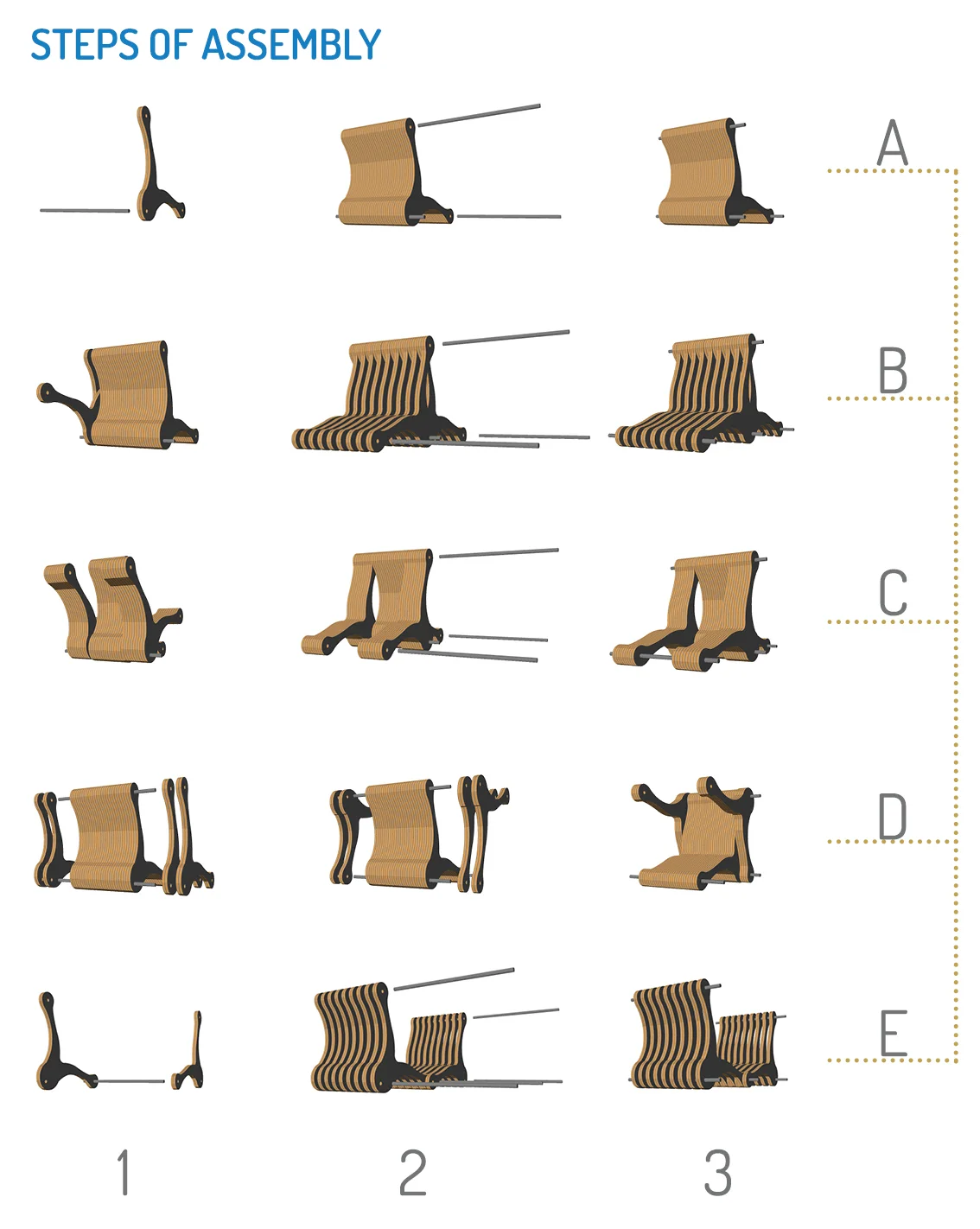
As shown in the large diagram, equal distances and shape of the modular form allowed it to be greatly interchangeable; the modules could be assembled into 5 different configurations (as shown in the assembly diagram). The assembly could adapt to the needs of its users according to its intended function and the amount of privacy required. The final modular design was lightweight, stackable, easy to assemble, multi-functional, very economical, weather-resistant, and had high vertical load capacity.
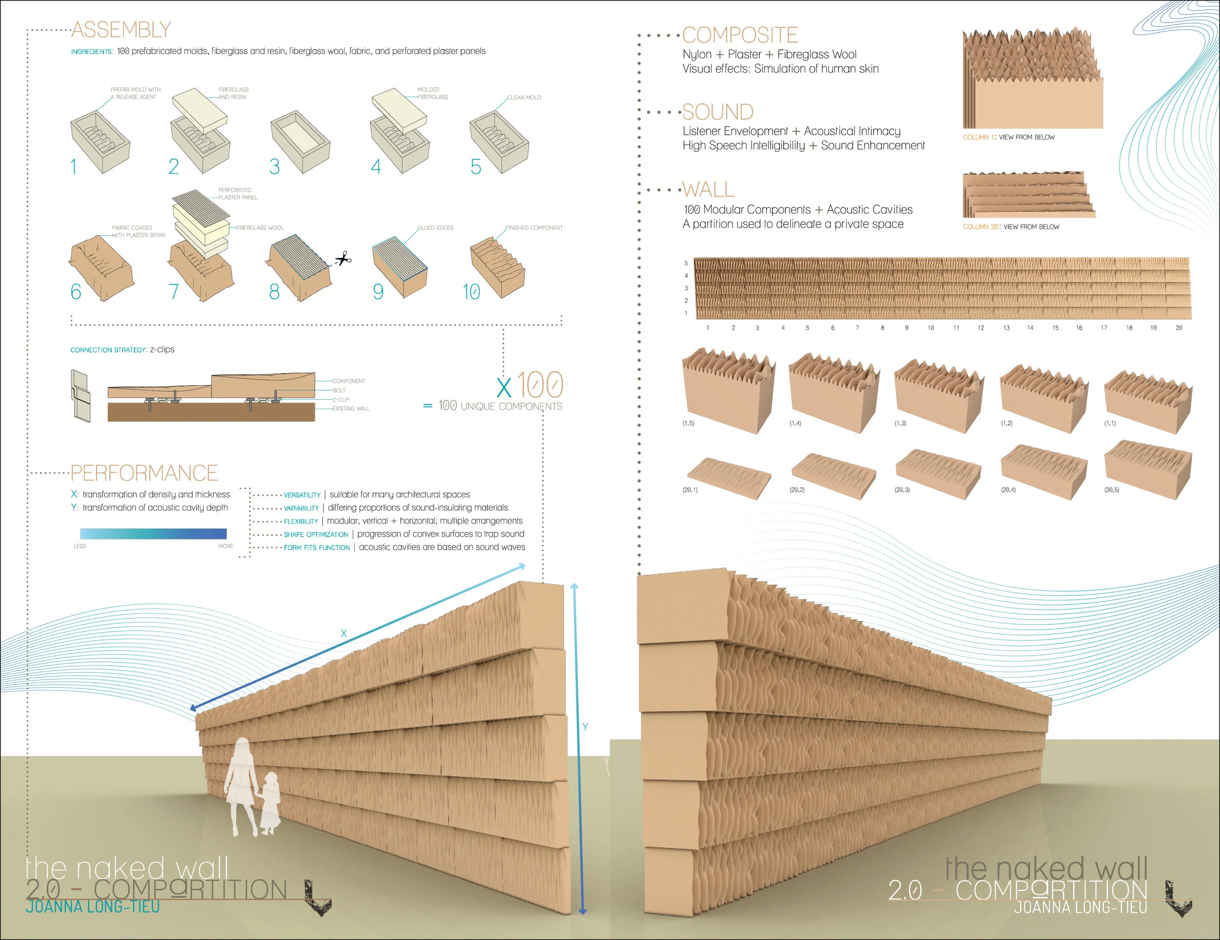
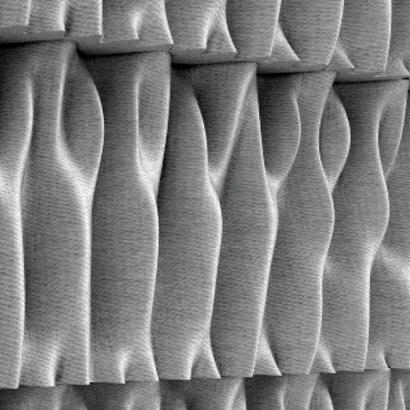
The objective of this assignment was to create a partition targeting one of the five sensory domains; I chose sound. The Naked Wall aimed to provide sound enhancement, privacy, and awe to its users by possessing both acoustical and aesthetic qualities.
The project developed over three design phases.
Board #1 (Phase 1):
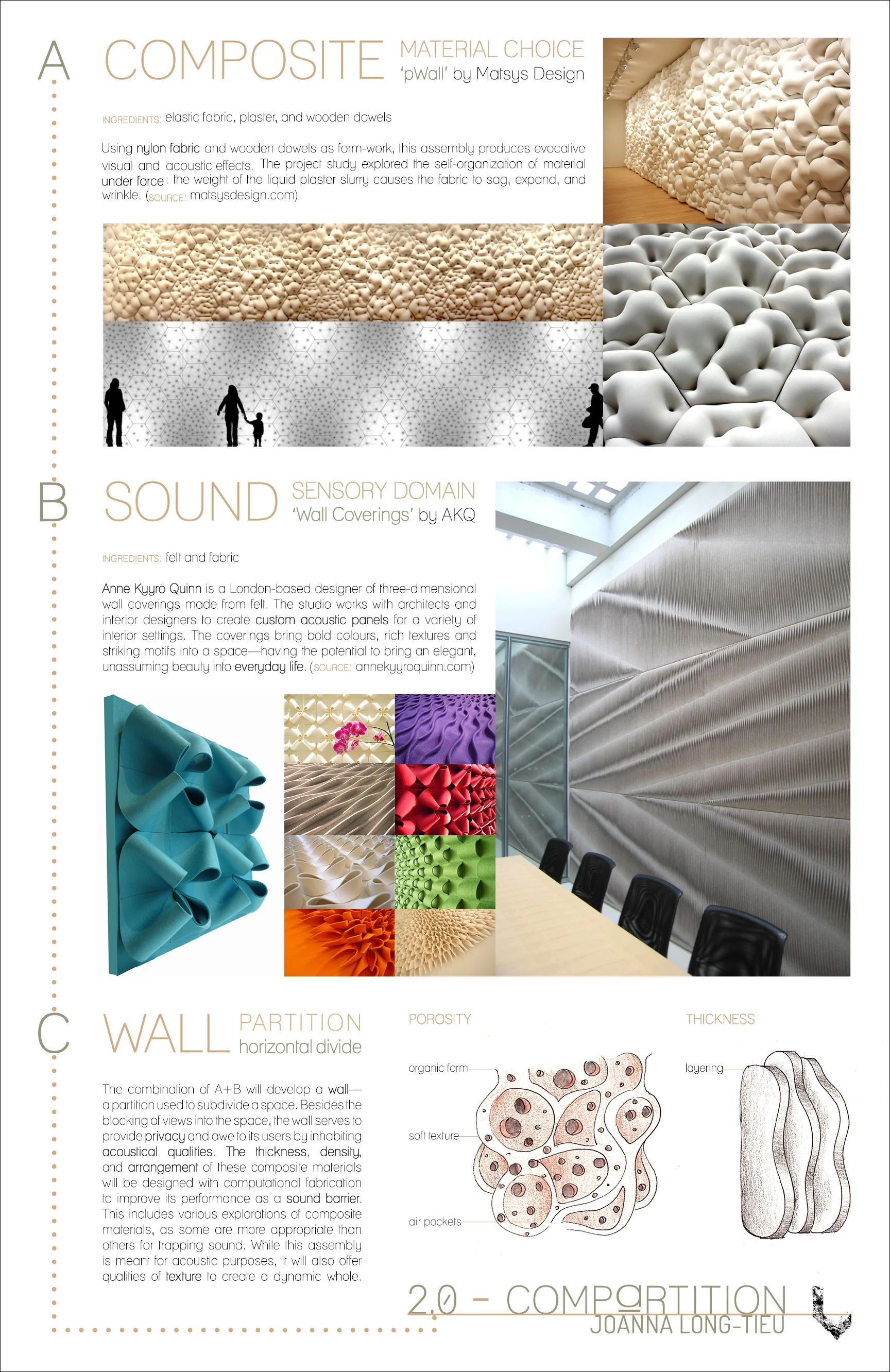
I explored two precedent studies: pWall by Matsys Design and Wall Coverings by AKQ. I was immediately drawn to the visual effects of the pWall—its soft, organic form had a skin-like appearance that seemed to sag, expand, and wrinkle. This unique aesthetic resulted from the self-organization of materials under force: elastic fabric, plaster, and wooden dowels. The AKQ Wall Coverings also had captivating visual effects, and their acoustic qualities were even more pronounced. These acoustic wall panels were constructed with layers of sound-insulating materials (felt and fabric), and surface textures were designed to trap sound.
The composite materials, acoustic performance, and aesthetic qualities from these two precedent studies informed the design process of the Naked Wall. The thickness, density, and arrangement of these composite materials would be tailored using computational fabrication to enhance its performance as a sound barrier. This involved further explorations of other composite materials, as some were better suited than others for sound insulation. The wall's formal and textural qualities were emphasized, not only to enhance its sound performance but also to captivate inhabitants with its organic visual effects. Additionally, porosity and thickness were crucial in determining the assembly's sound performance.
Boards #2 and #3 (Phase 2):
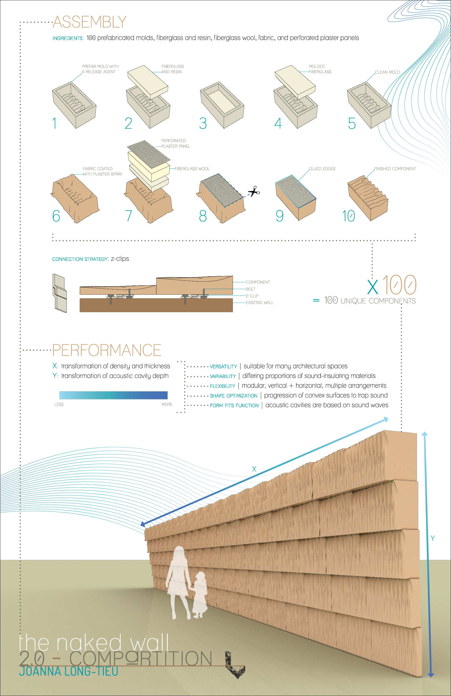
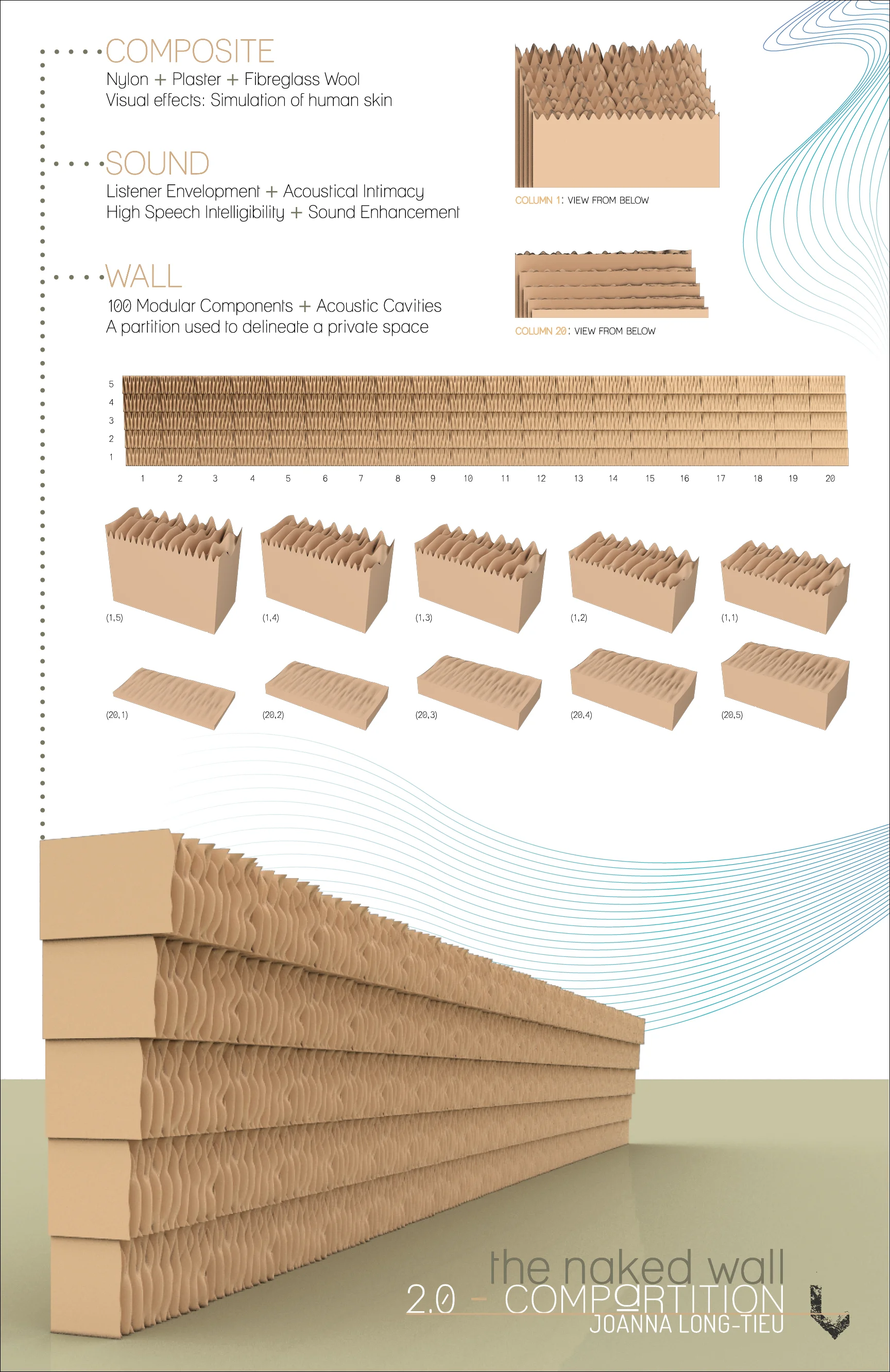
The assembly and performance of the wall were honed in the second phase. Composite materials of nylon, plaster, and fiberglass wool simulated human skin. This provided the following acoustic qualities: listener envelopment, acoustical intimacy, high speech intelligibility, and sound enhancement. The assembly comprised 100 modular components with acoustic cavities and was designed as a partition to mark a private space.
The fabrication process for each modular component was outlined in 10 sequential steps: using 100 prefabricated molds, fiberglass and resin, fiberglass wool, fabric, and perforated plaster panels. Each module was unique, with variances in its X and Y dimensions. The further down the module sat on the partition along the X-axis, the thicker and denser it became. Moving further up along the Y-axis yielded modules with increased acoustic cavity depth.
Z-Clips served as the connection strategy between each module (as illustrated in a section drawing).
Board #4 (Phase 3):
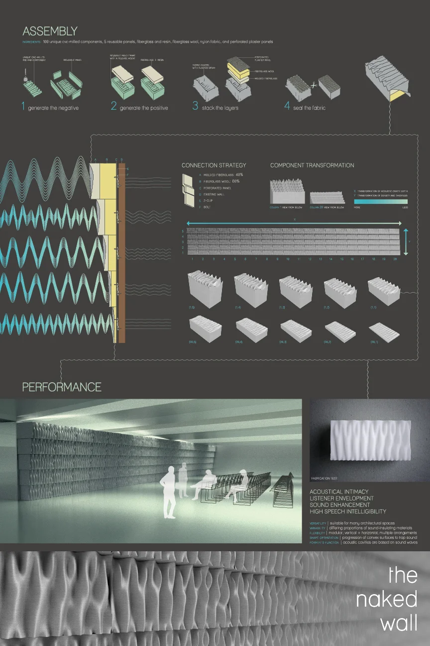
The amount of work required to assemble each module was reduced to just 4 steps in the final phase, with a keen focus on sustainable material usage. 100 unique CNC-milled prefabricated components (with acoustic cavities) and 4 reusable side panels replaced the 100 prefabricated molds from Phase 2. A reusable mold frame was also developed to reduce material costs.
The Naked Wall was covered in a soft, neutral-gray fabric, making it versatile and suitable for various architectural contexts. Its overall acoustic performance was adaptable, offering different mixes of sound-insulating materials. Its aesthetic was also highly flexible due to its modular nature: the modules could be oriented either vertically or horizontally, and the arrangement could vary in multiple ways. The trapping of sound in the convex surfaces paved the way for shape optimization. Furthermore, the organic shape of the acoustic cavities resulted from merging sound wave patterns, ensuring the form followed function.
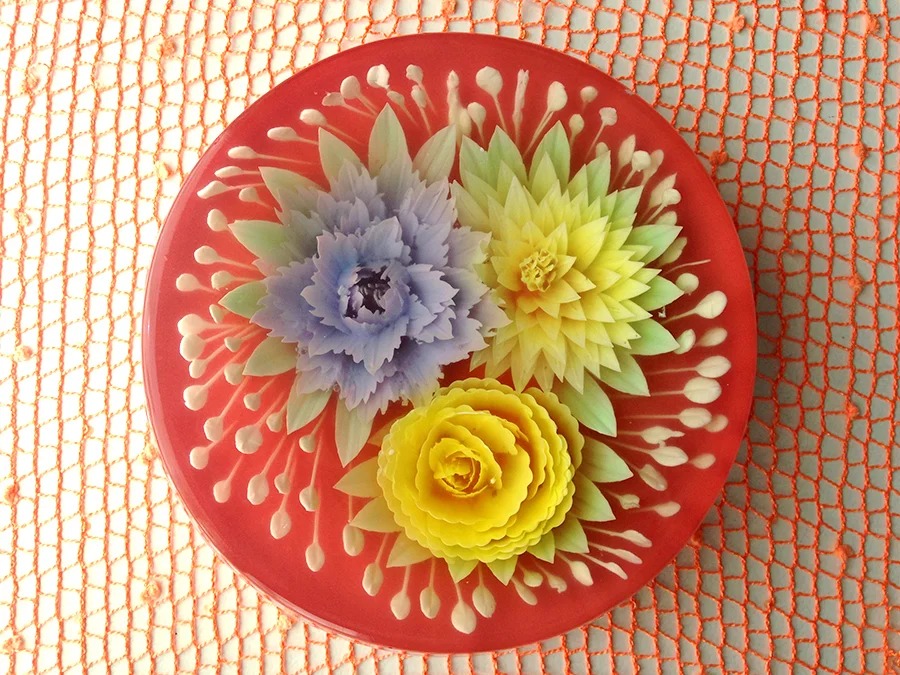
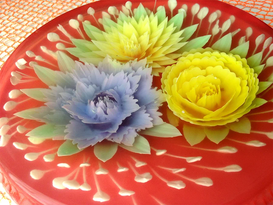
I turn towards Nature when I need inspiration for creativity. It has always been one of my guiding principles in creating aesthetic and functional design. I have a deep-rooted love for Nature, and I illuminated its sacredness by encapsulating 3D flowers underneath a flat cylinder plane. Everything is impermanent. Like real flowers (or any form of life), this art piece was only temporary—it was fully biodegradable.
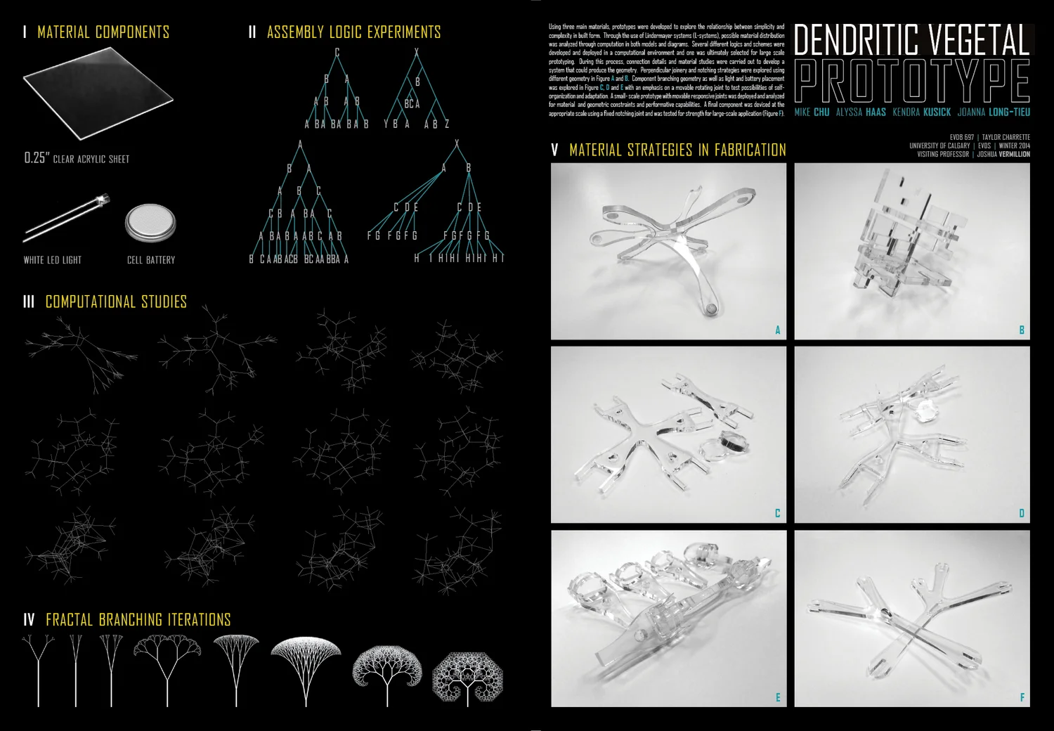
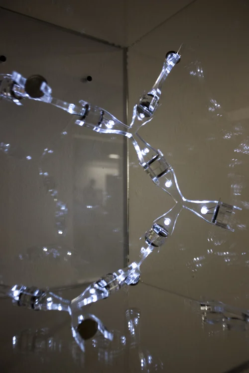
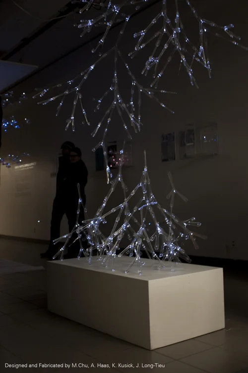
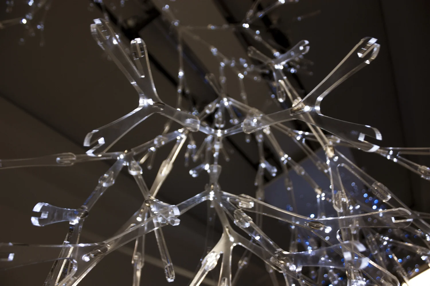
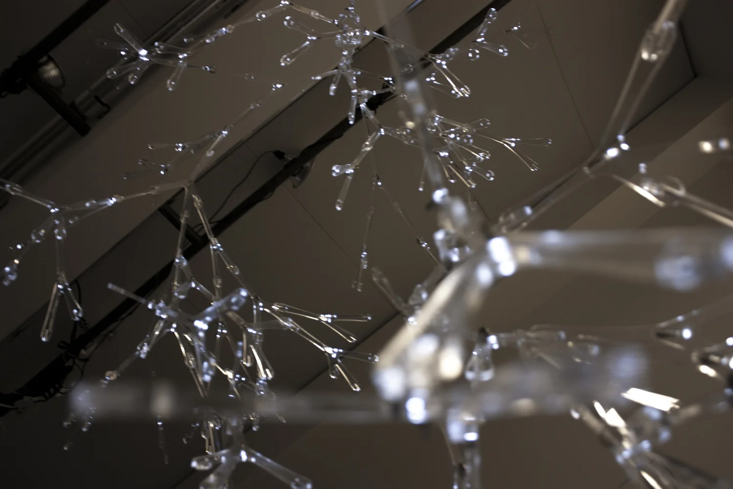
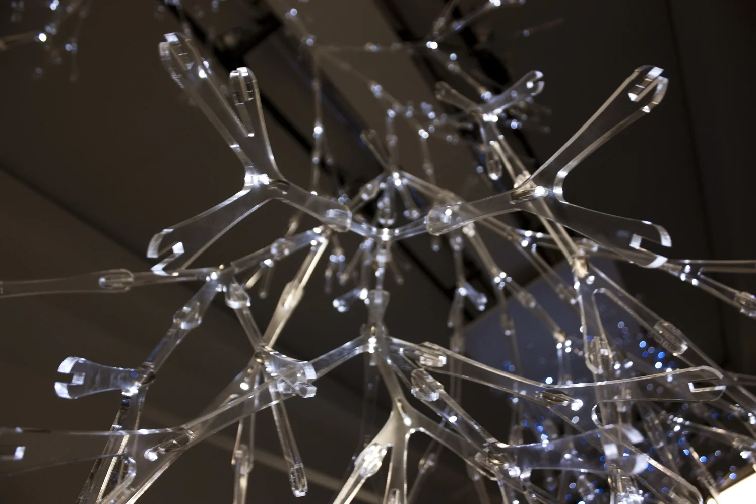
Using three primary materials, prototypes were developed to explore the relationship between simplicity and complexity in built form. Through the use of Lindermayer systems (L-systems), possible material distribution was analyzed computationally in both models and diagrams. Several different logics and schemes were developed and deployed in a computational environment, and one was ultimately selected for large-scale prototyping. During this process, connection details and material studies were carried out to develop a system that could produce the geometry. Perpendicular joinery and notching strategies were explored using different geometries in Figures A and B. Component branching geometry, as well as light and battery placement, was explored in Figures C, D, and E, with an emphasis on a movable rotating joint to test possibilities of self-organization and adaptation. A small-scale prototype with movable responsive joints was deployed and analyzed for material and geometric constraints and performative capabilities. A final component was devised at the appropriate scale using a fixed notching joint and was tested for strength for large-scale application (Figure F).
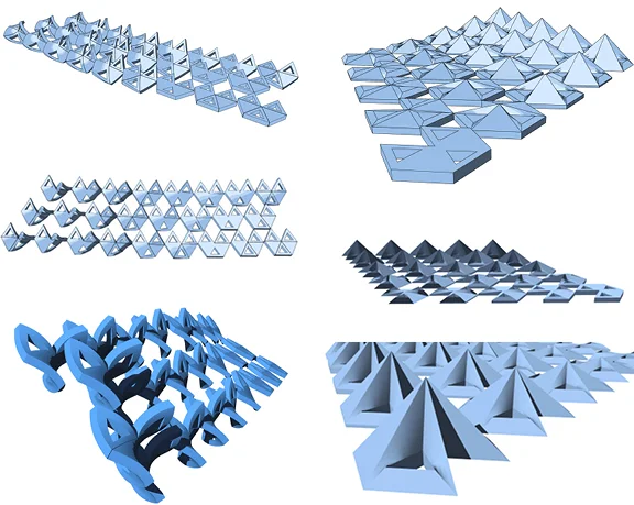
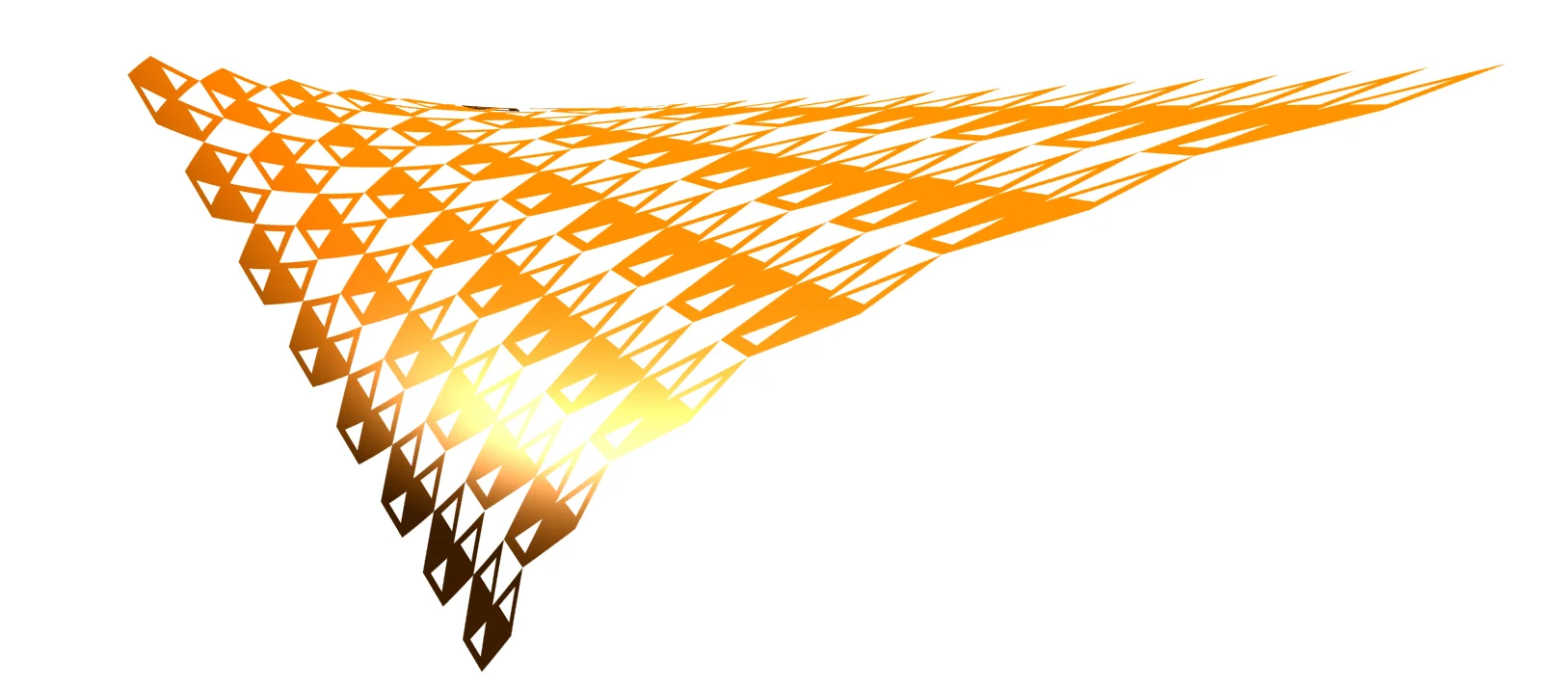
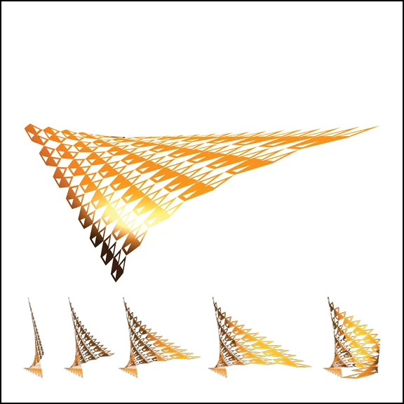
Featherwing resulted from the comprehensive exploration and development of a single base component over three design phases (1.1, 1.2, and 1.3). The transformation of the component and its corresponding assembly was based on the application of specific rules. This strategy allowed the design to evolve computationally in Grasshopper. As illustrated in the subsequent boards, the processes of creasing, twisting, extruding, and scaling down determined the overall functionality and versatility of the computed assemblies.
Board #1: 1.1 REVERSE ENGINEERING
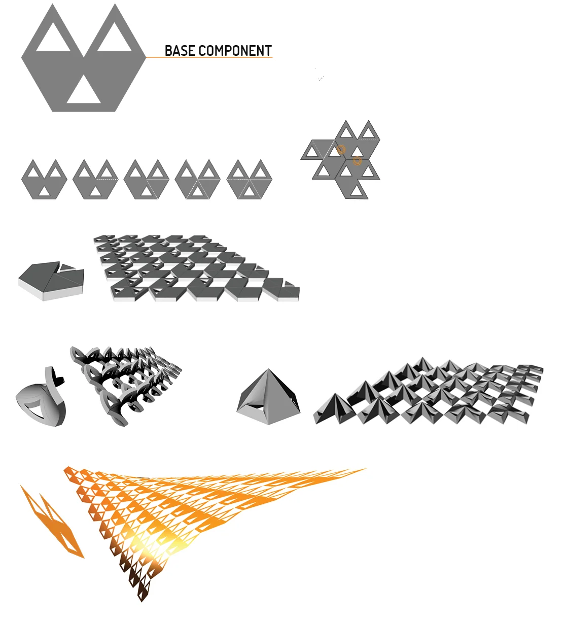
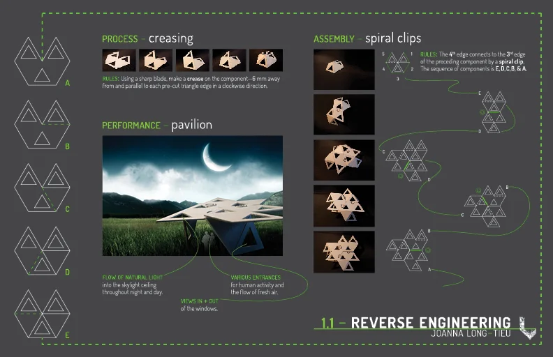
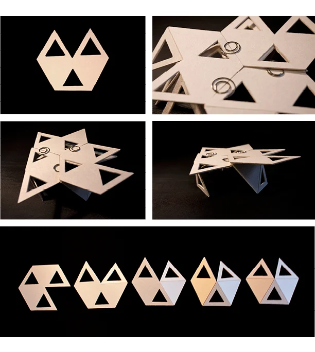
A 7-sided polygon with triangular features was designed as the base component. The process of creasing was applied to the component with the following rules: using a sharp blade, make a crease on the component: 6mm away from and parallel to each pre-cut triangle edge, in a clockwise direction. This rule was applied to the base component until a maximum of 5 unique components were created. These 5 components were assembled according to a new set of rules: The 4th edge connects to the 3rd edge of the preceding component via a spiral clip. The sequence became E, D, C, B, and A—resulting in a self-organized form that depicted the performative qualities of a pavilion. The pre-cut triangles served three distinct functions: allowing for the flow of natural light into the skylight ceiling, providing views in and out of the windows, and offering various entrances for human activity and fresh air circulation.
Board #2: 1.2 MODEL CITIZEN
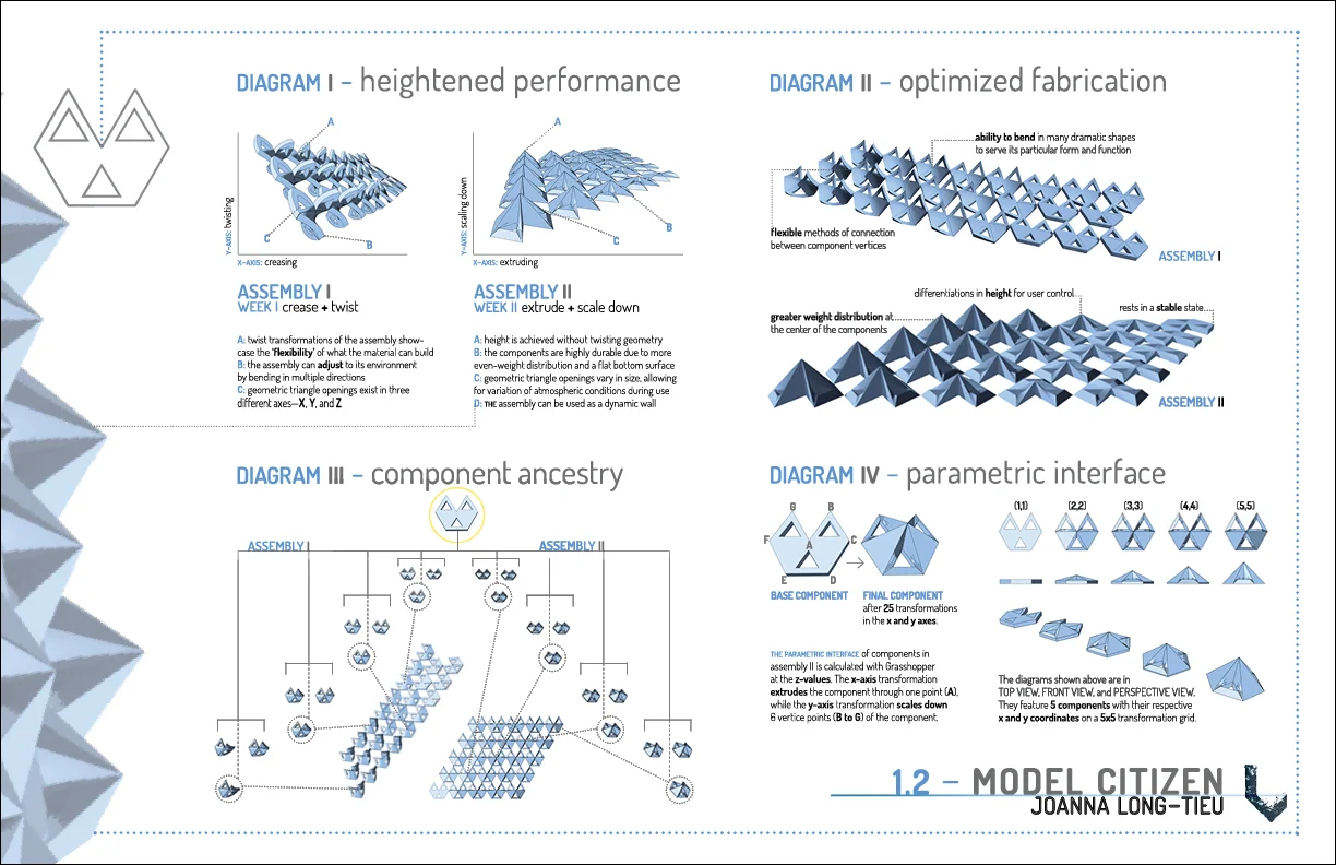
In the second phase, the component also adhered to a set of rules, but now the changes occurred in 3D space (along the X, Y, and Z axes).
As depicted in DIAGRAM I, the component underwent two sets of heightened performance explorations: crease + twist and extrude + scale down. This resulted in the emergence of distinct performative aspects within the two assemblies. In ASSEMBLY I, the twist transformations highlighted the material's build flexibility and its ability to adapt to its environment by bending in multiple directions. In ASSEMBLY II, height was achieved without the need for twisting geometry. The components were especially durable due to an even weight distribution and a flat bottom surface. Additionally, the geometric triangle openings varied in size, allowing for diverse atmospheric conditions during its use.
Alternative views were presented in DIAGRAM II to emphasize the strengths of these two assemblies, with fabrication taken into account. Because ASSEMBLY I allowed for flexible methods of connection between component vertices, it could assume many dramatic shapes to fulfill its specific form and function. ASSEMBLY II featured a more centralized weight distribution in its components, ensuring stability. The differentiation in height provided users with more control during the fabrication process.
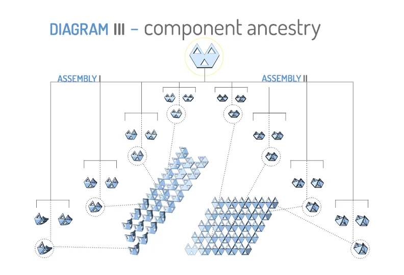
In DIAGRAM III, four specific components (plus the main base component) from both assemblies were computationally mapped to study and compare their parametric relationships.
The five components derived from the ancestry tree in ASSEMBLY II were then examined more closely to inspect its parametric interface. The transformations of extruding and scaling down became significantly clearer when the five components were aligned side by side.
Boards #3 and #4: 1.3 THE 7-SYLLABLE ASSIGNMENT
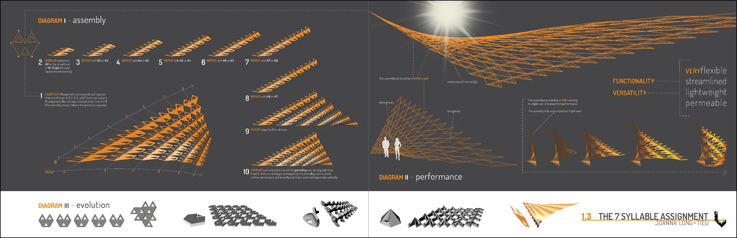
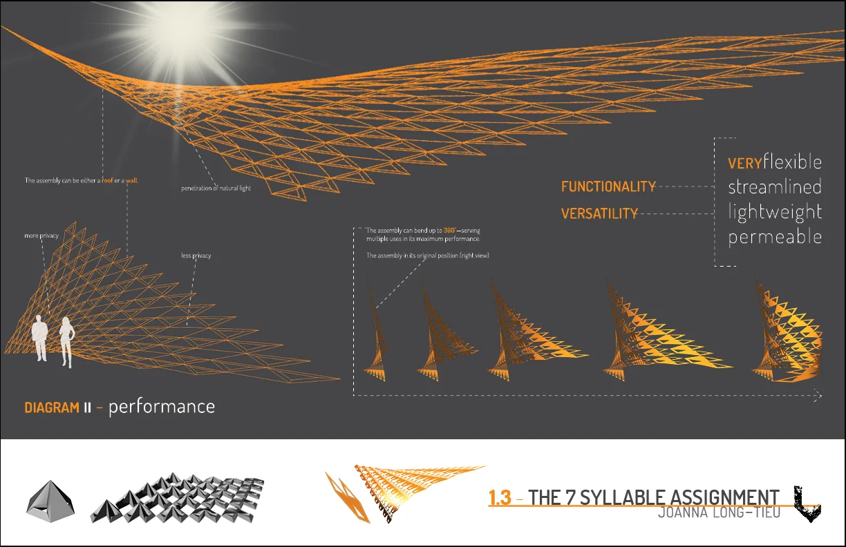
The comprehensive insights from phases 1.1 and 1.2 led to the conception of Featherwing. The base component was subjected to the straightforward computational rules of scaling down along both axes to optimize its functional and versatile performance.
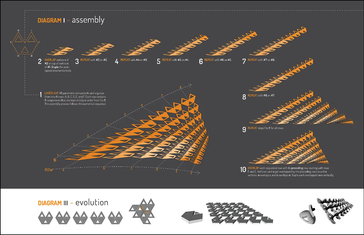
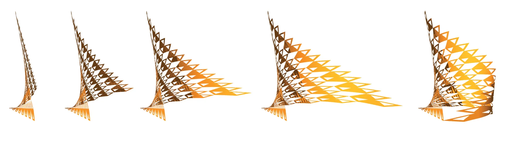
DIAGRAM I outlines the 10 steps necessary to connect the 48 parametric components together. The final assembly was remarkably flexible, streamlined, lightweight, and permeable, even though the components did not undergo the processes of creasing, twisting, or extruding. As showcased in DIAGRAM II, Featherwing could bend 360°, maximizing its utility. The assembly could function as either a roof or a wall, with the range of openings modulating the penetration of natural light and user privacy.
Still Life #1: MAGICAL PEARS
White conté and chalk on black construction paper
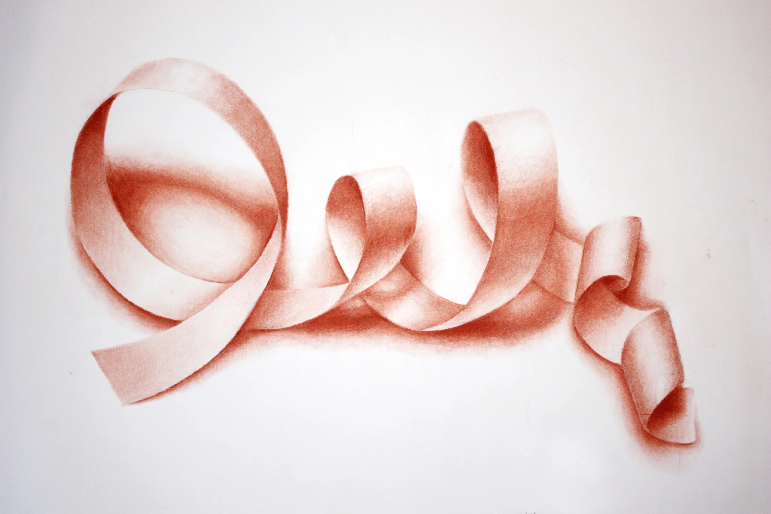
Still Life #2: RUSTY PAPER RIBBON
Burnt Sienna conté on white vellum paper
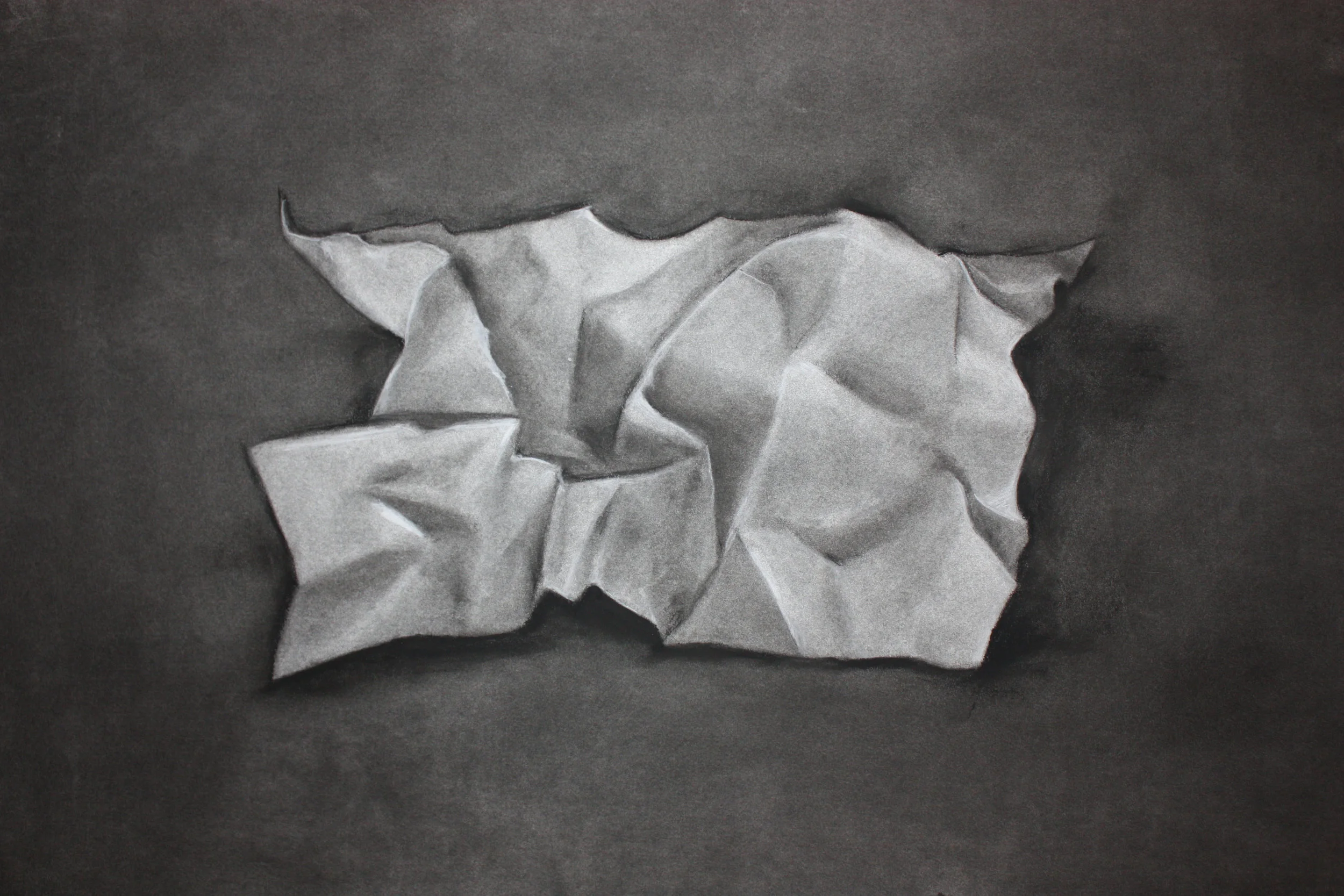
Still Life #3: CRUMPLED PAPER
Erasing powdered charcoal on white vellum paper
Booklet #1: SPRING INTO ACTION!
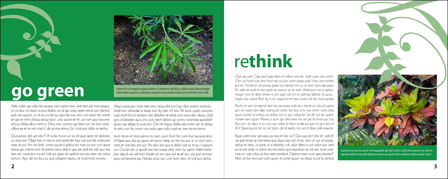
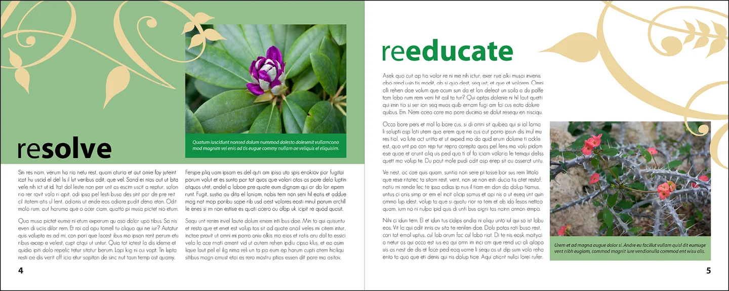
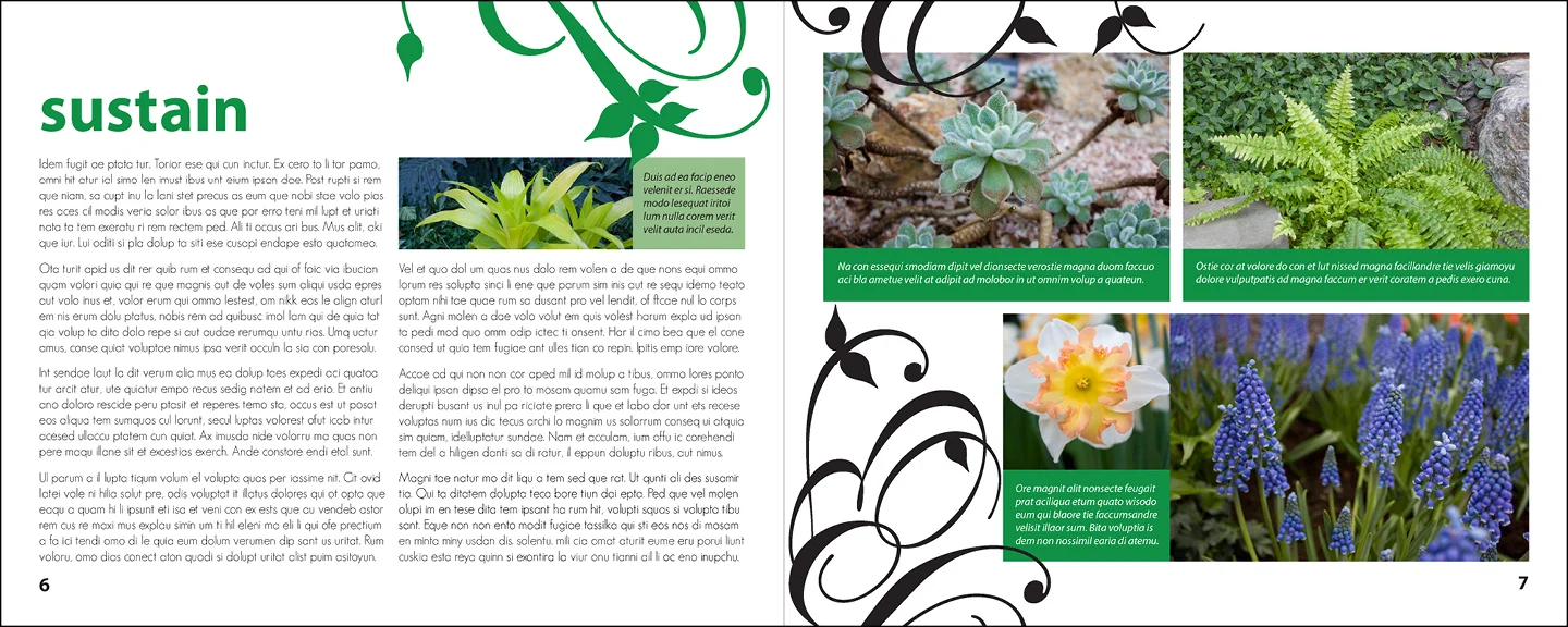
This booklet served as a template for the non-profit organization at the University of Alberta—ECOS (Environmental Coordination Office of Students)—to promote their Campus Community Garden. The objective of this campaign was to motivate the public to learn, teach, and sustain proper methods for preserving plants in the environment.
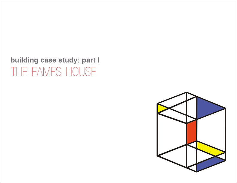
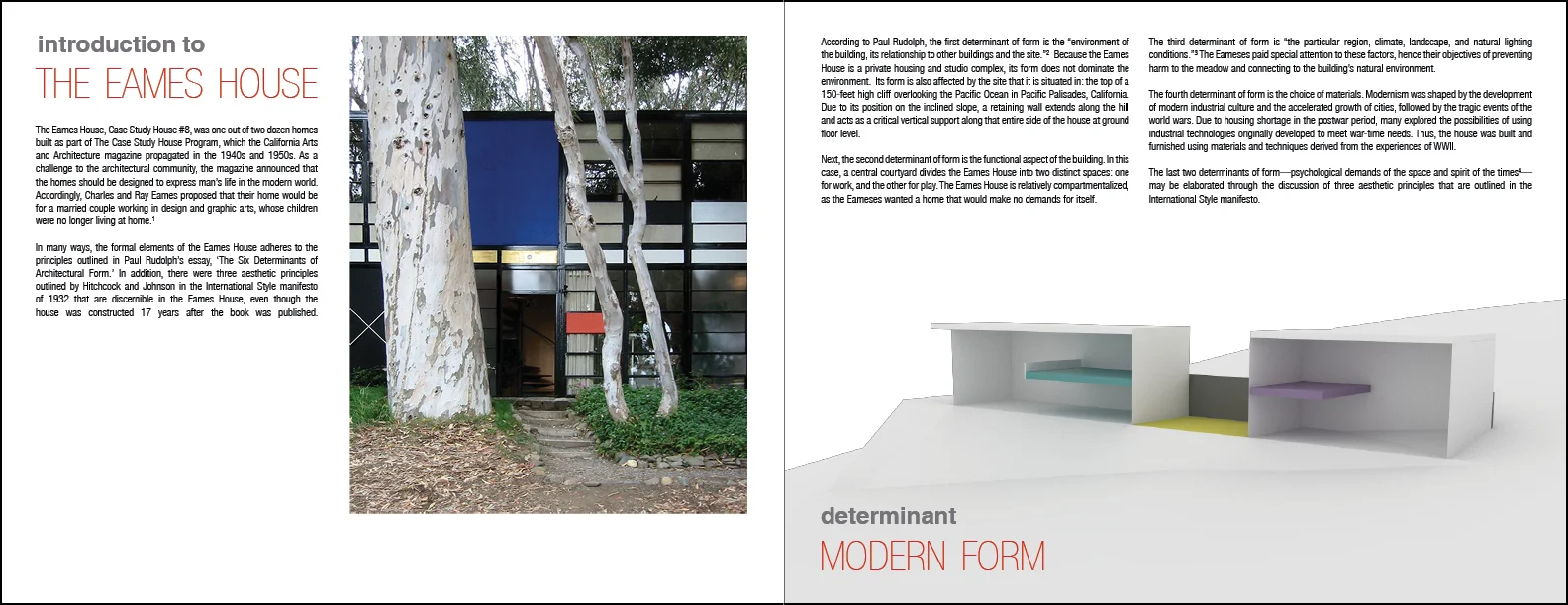
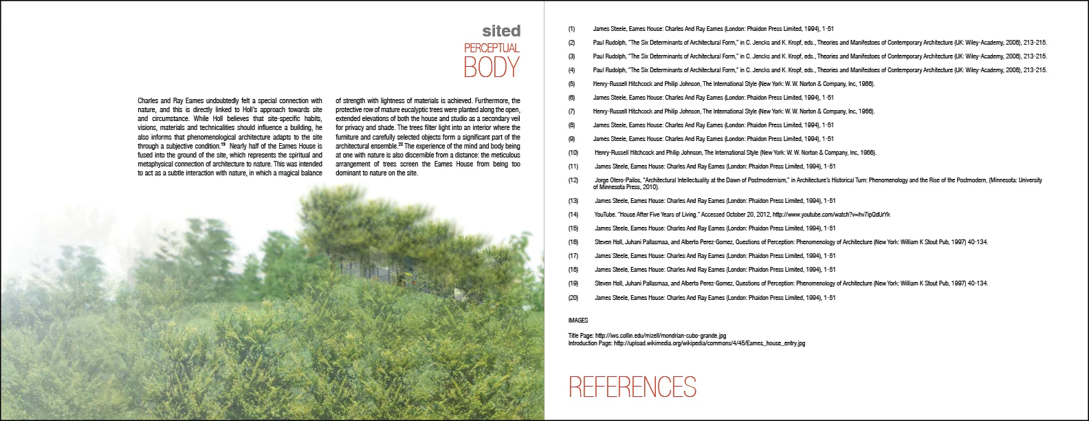
Booklet #2: BUILDING CASE STUDY OF THE EAMES HOUSE
The purpose of this case study project was to explore the form-body of a selected building. I chose the Eames House because I was curious about the lives of Charles and Ray Eames—a married couple who worked with art & design and whose children no longer lived with them.
I was also attracted to its historical context. Modernism was shaped by the evolution of modern industrial culture, the rapid growth of cities, and the tragic events of the world wars. Due to housing shortages in the postwar period, many explored the possibilities of employing industrial technologies that had been developed to address wartime needs. As a result, the house was constructed and furnished using materials and techniques drawn from the experiences of WWII.
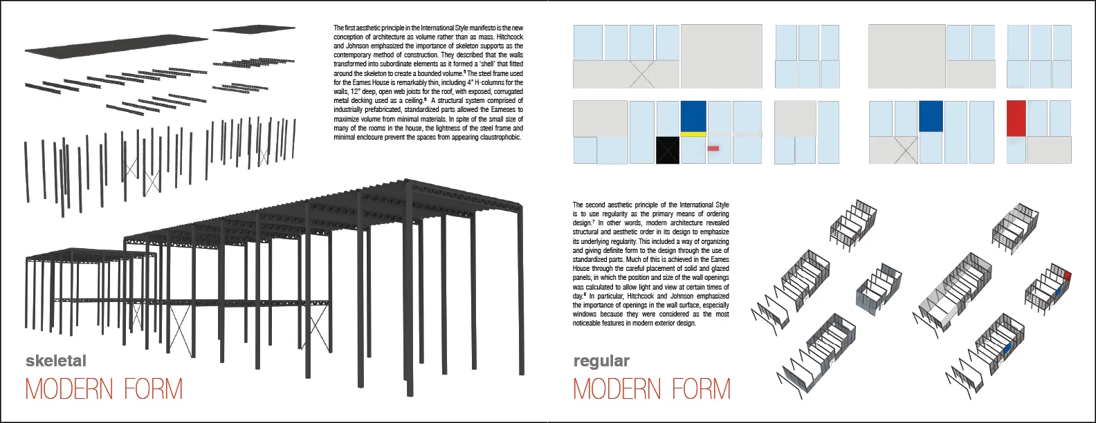
The formal elements of this house were influenced by the principles outlined in Paul Rudolph’s essay, ‘The Six Determinants of Architectural Form’:
the building's environment / its relationship to other structures and the site
the functional aspect of the building
the specific region, climate, landscape, and natural lighting conditions
the choice of materials
the psychological demands of the space
the zeitgeist or spirit of the times
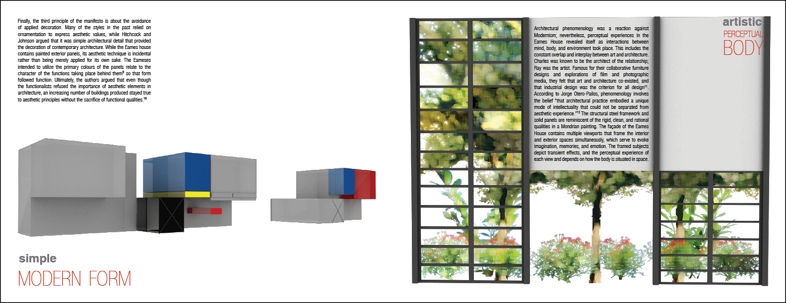
Three aesthetic principles outlined by Hitchcock and Johnson in the International Style Manifesto of 1932 were also evident in the Eames House:
a new conception of architecture as volume rather than mass
regularity as the primary means of ordering design
the avoidance of applied decoration
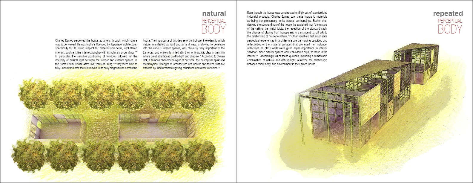
Although architectural phenomenology was a reaction against Modernism, the Eames House revealed perceptual experiences as interactions between the mind, body, and environment occurred. This included a continuous interplay between art and architecture.
The content of this booklet drew upon the principles mentioned above to guide the reader through the construction and experiences of the architectural space. The goal was to offer a deconstructed perspective on how Modernism influenced the formal and aesthetic sensibilities of the architectural community during that era. Moreover, the objective was to give the reader an intimate glimpse into Charles and Ray Eames' life in a Modern world.
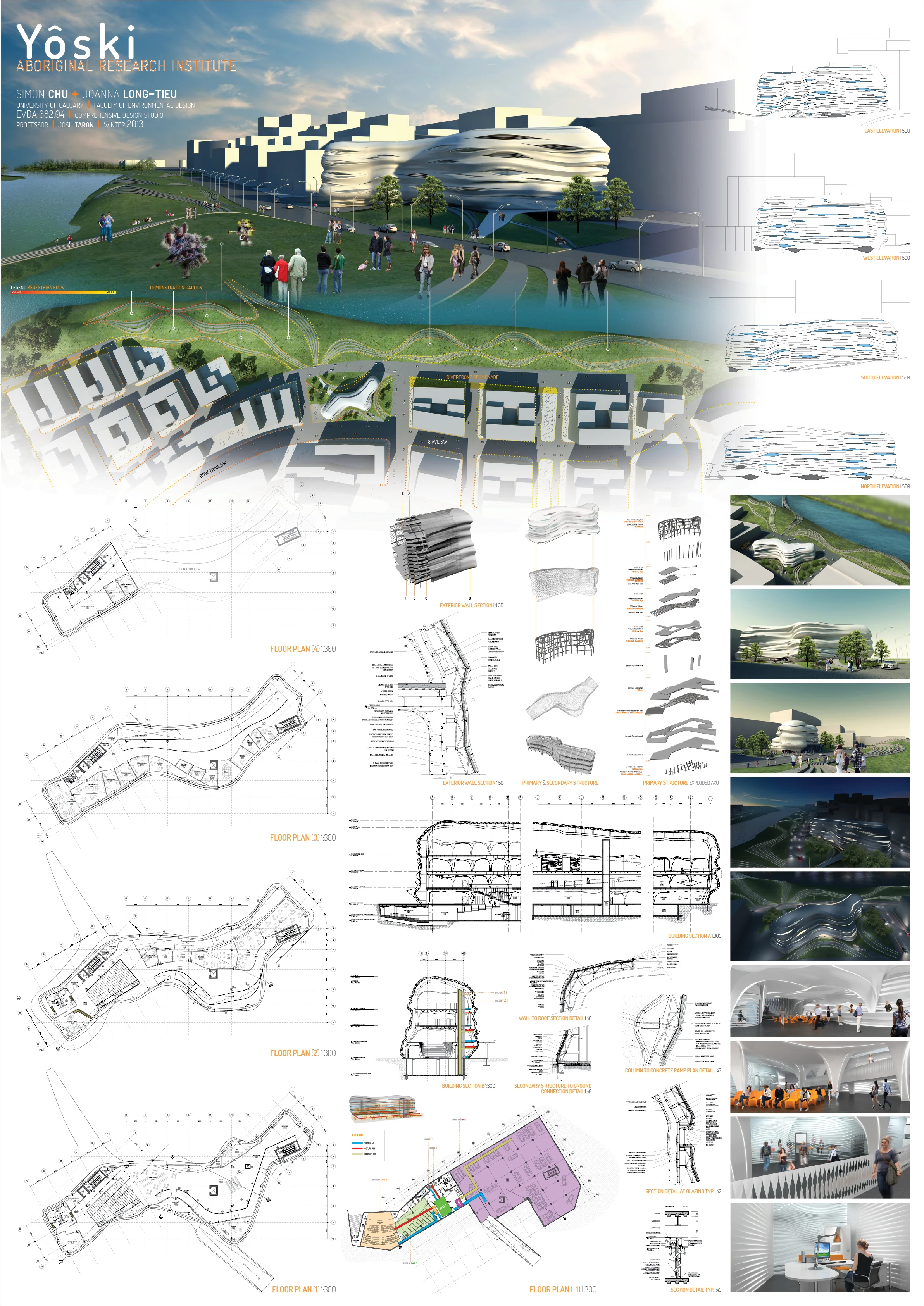
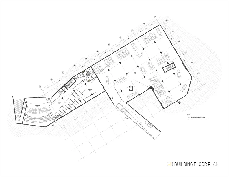
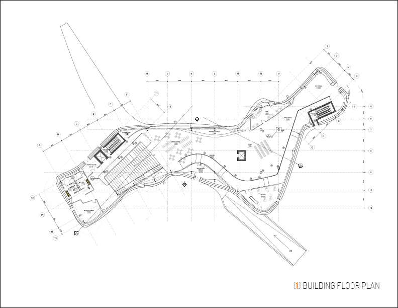
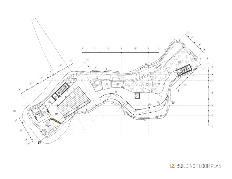
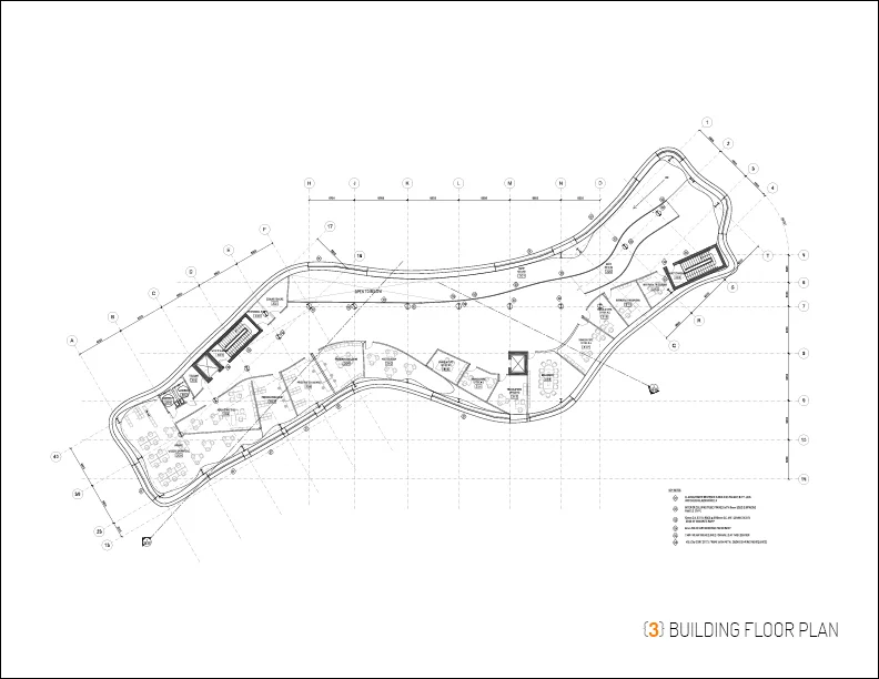
COMPREHENSIVE STUDIO PROJECT
In collaboration with Simon Chu
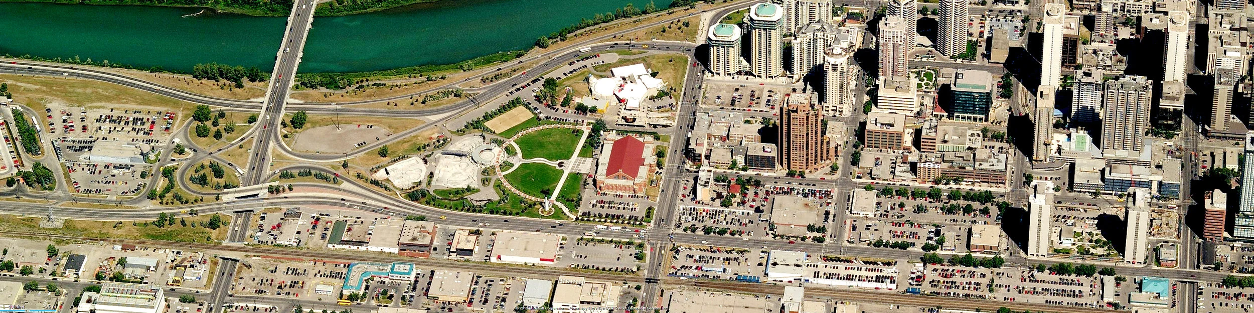
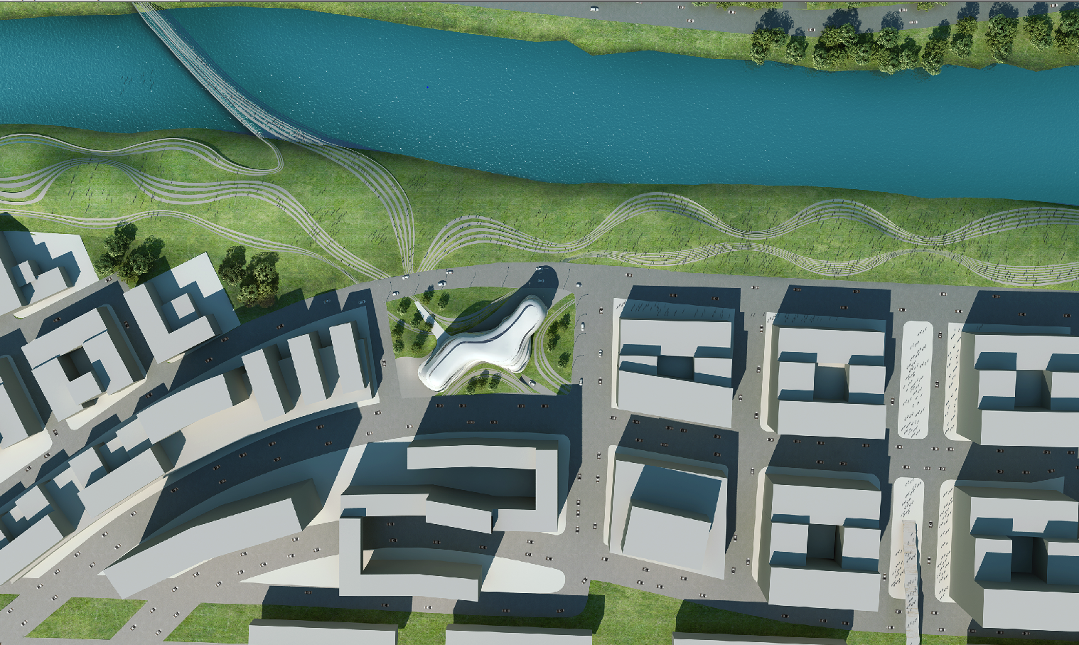
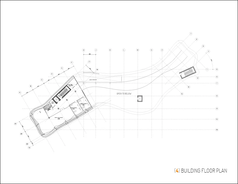
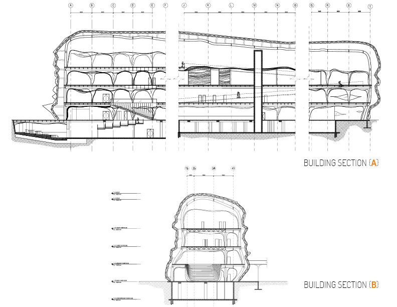
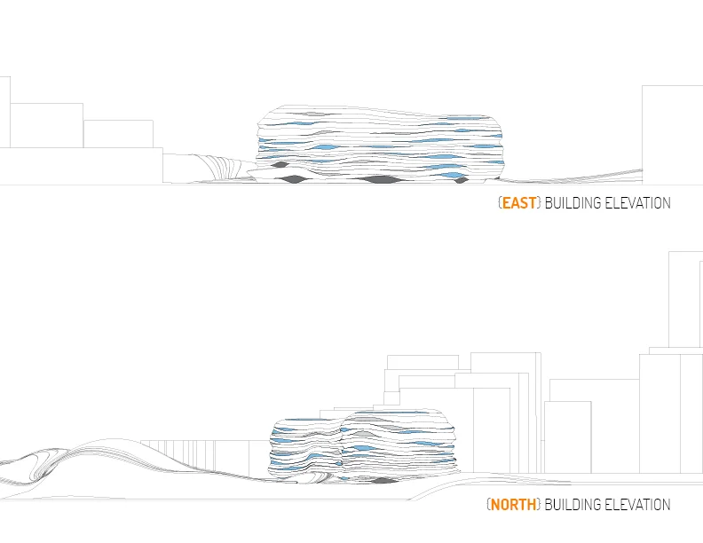
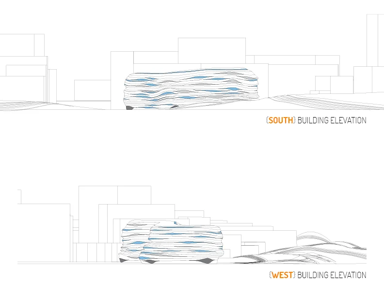
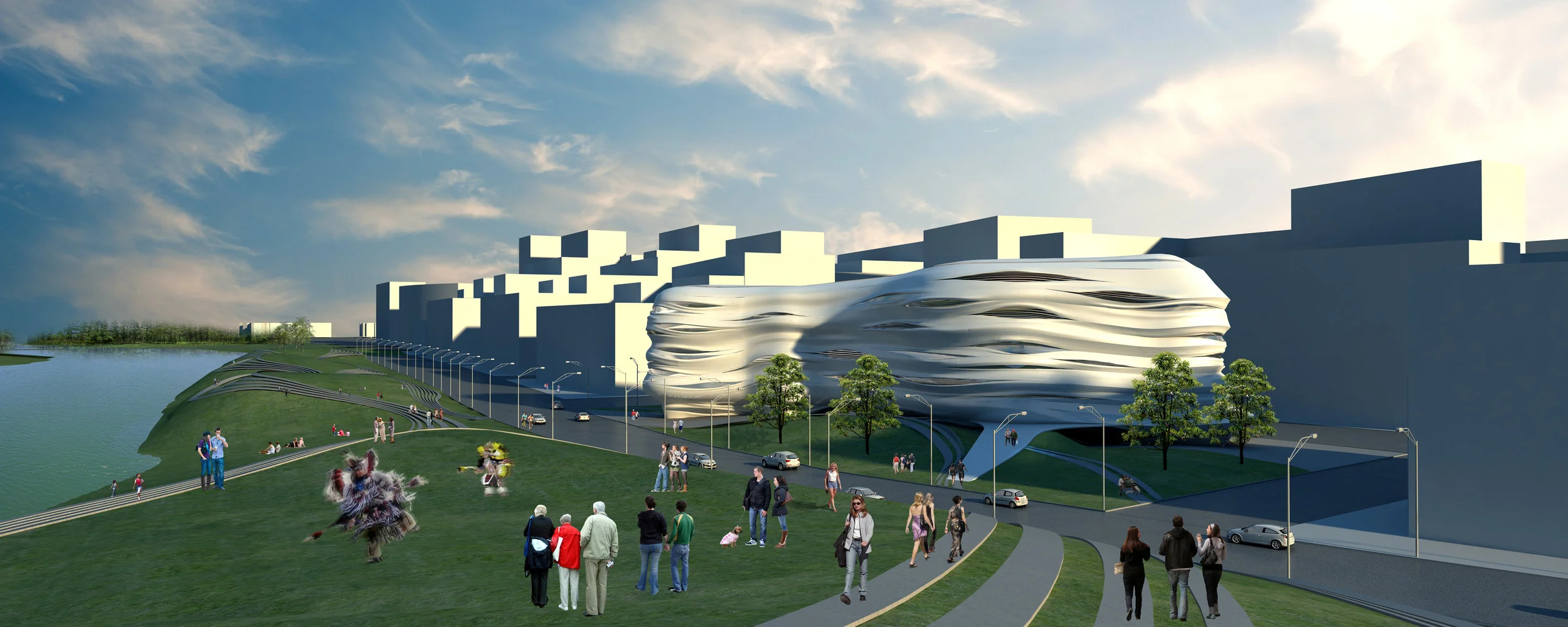
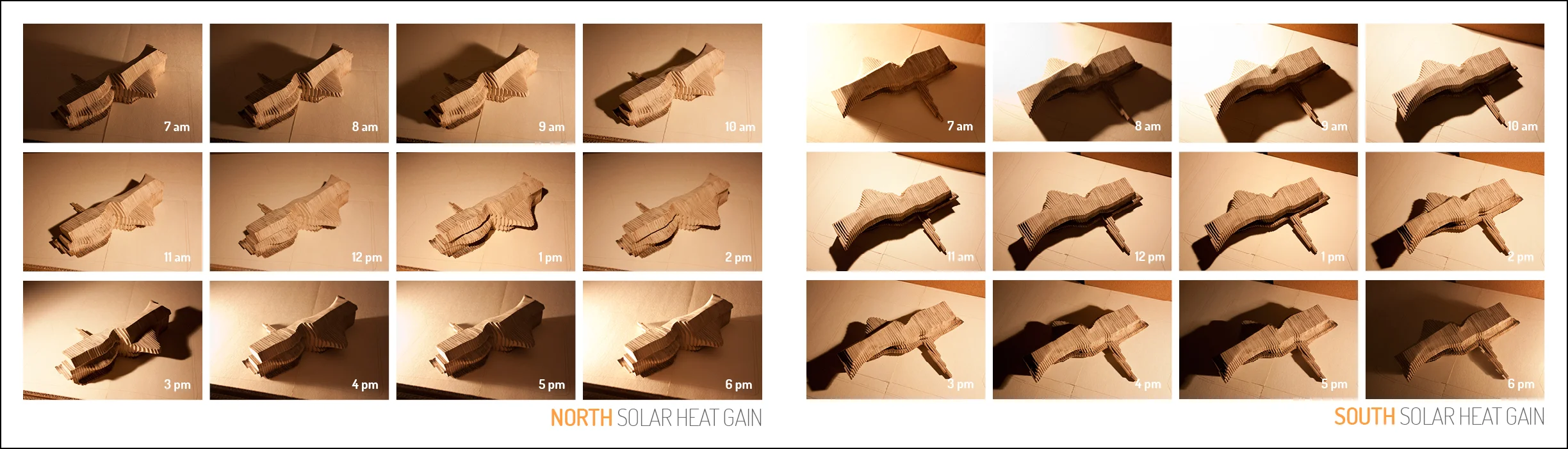
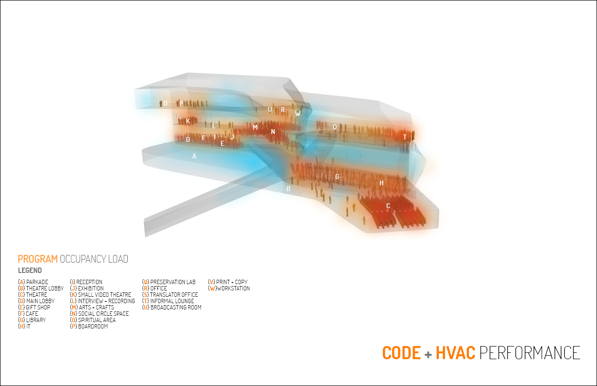
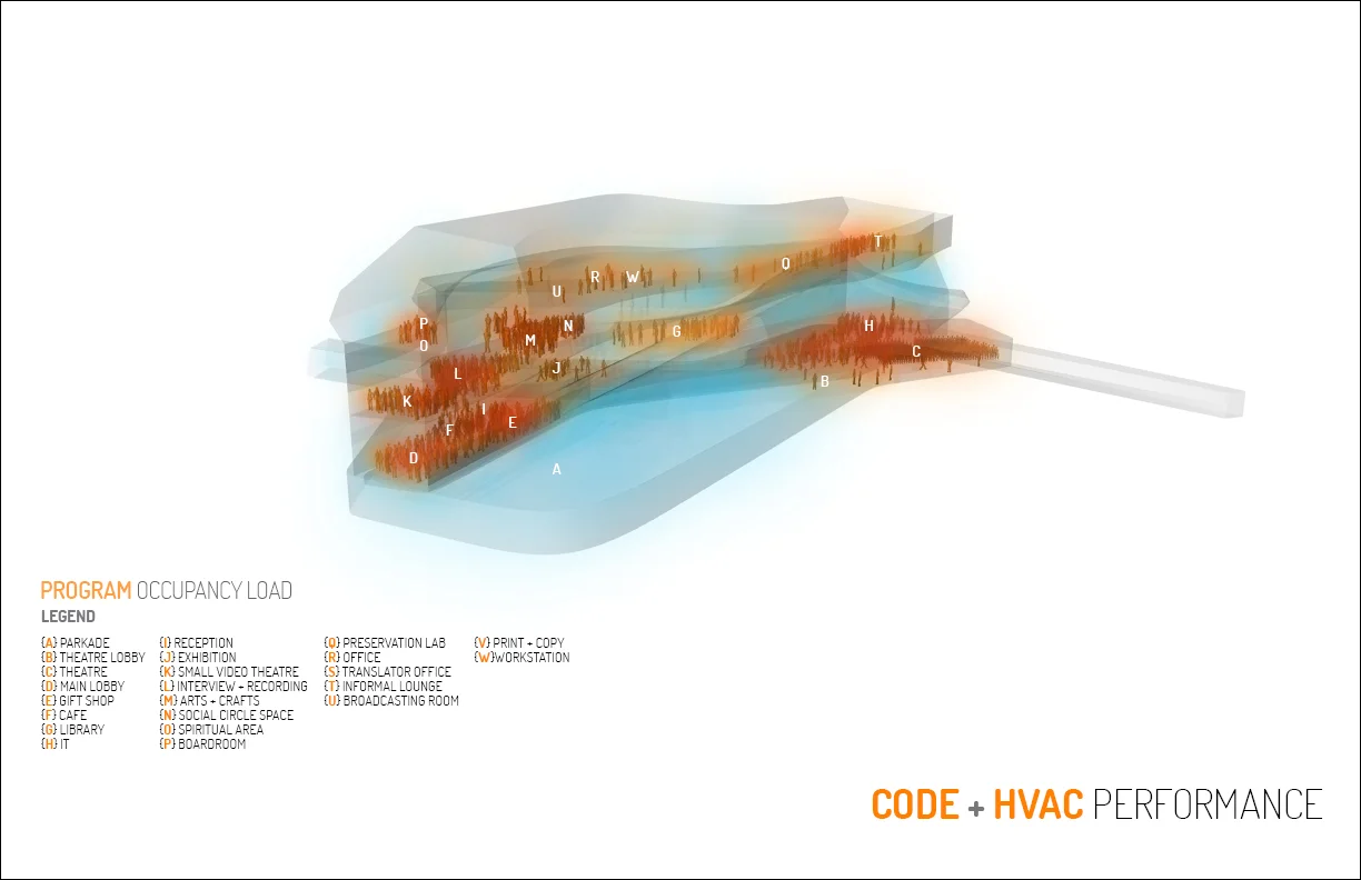
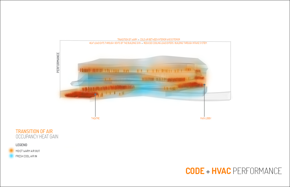
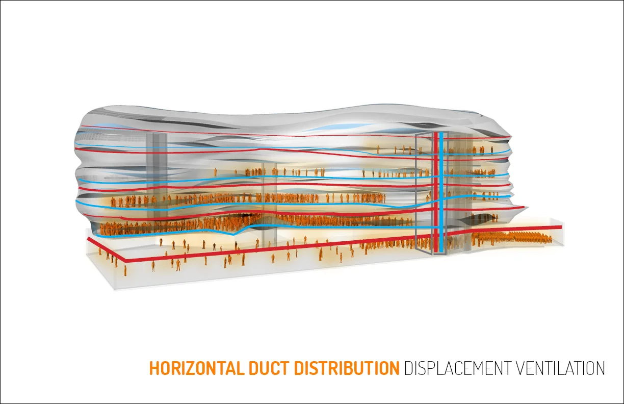
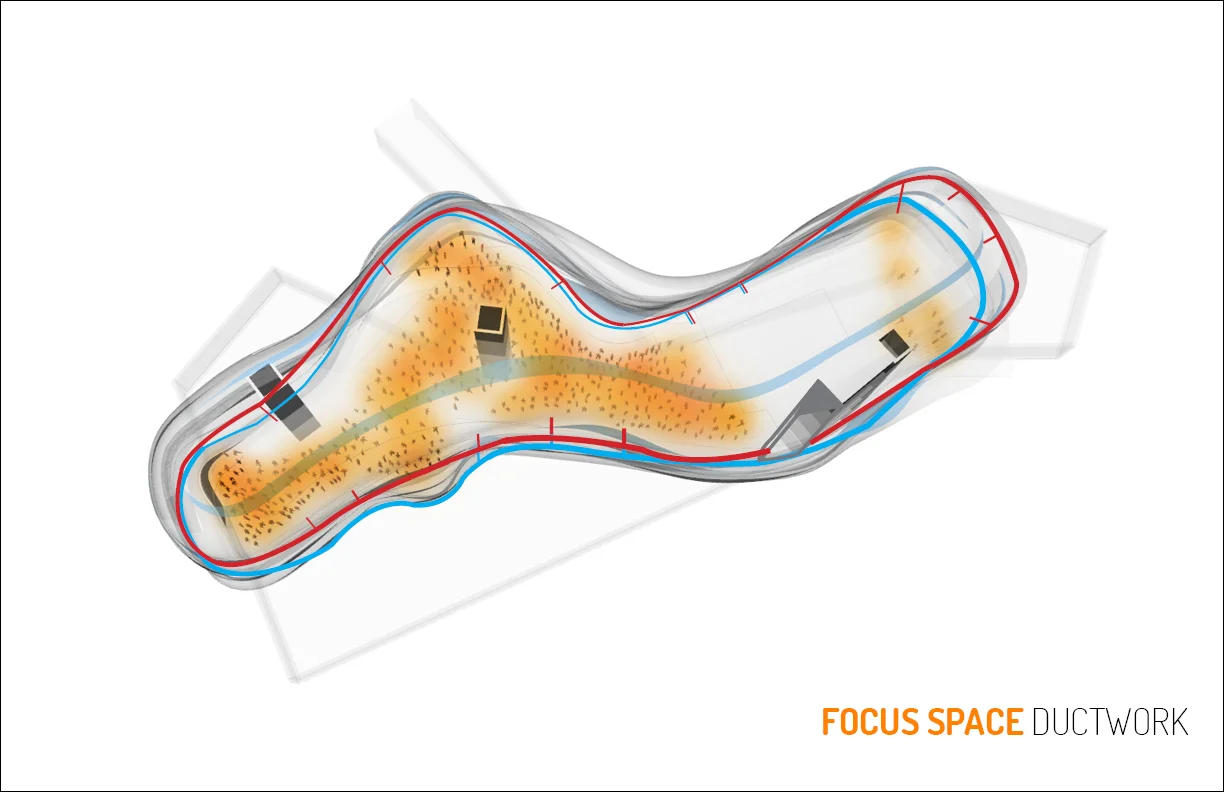
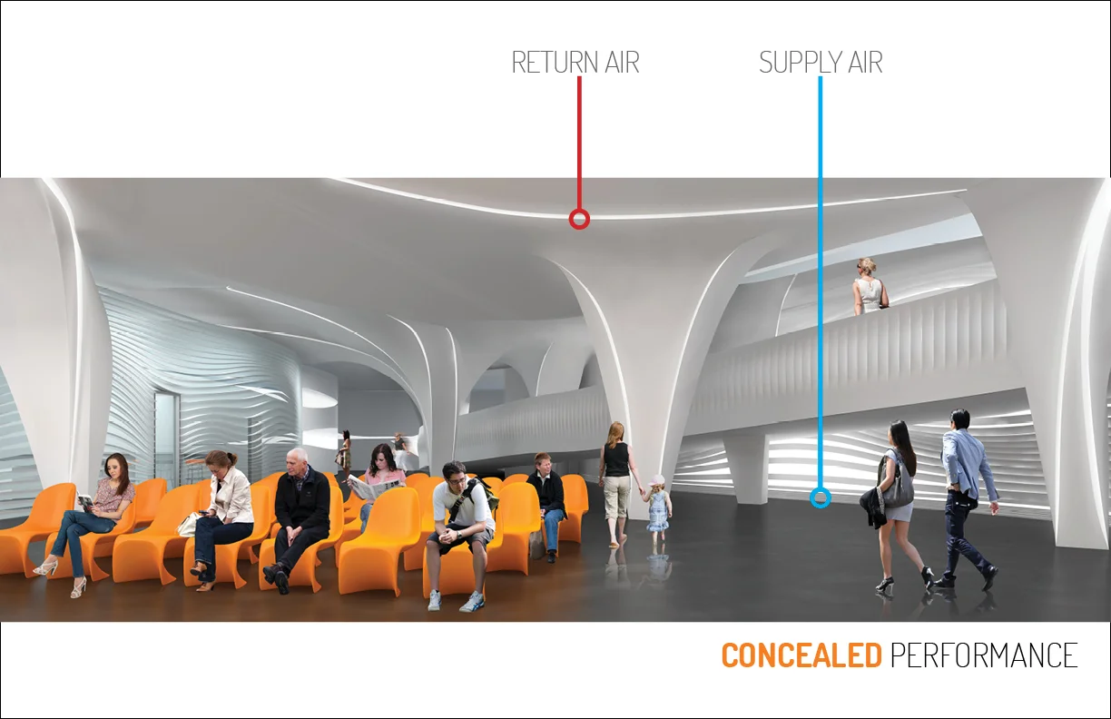
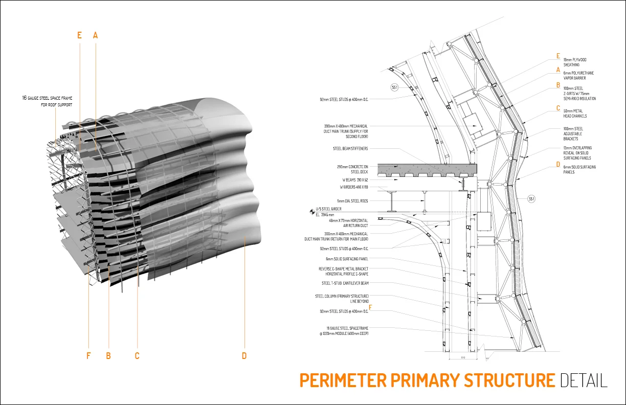
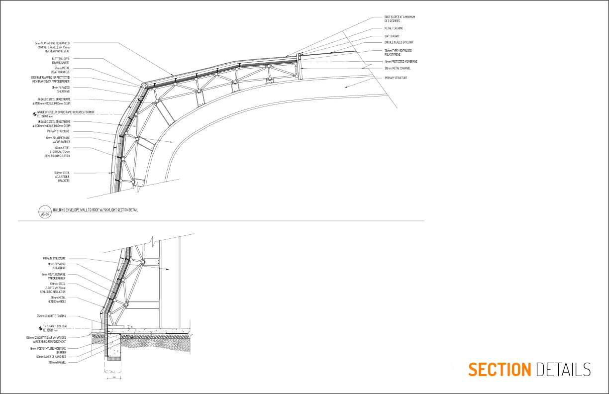
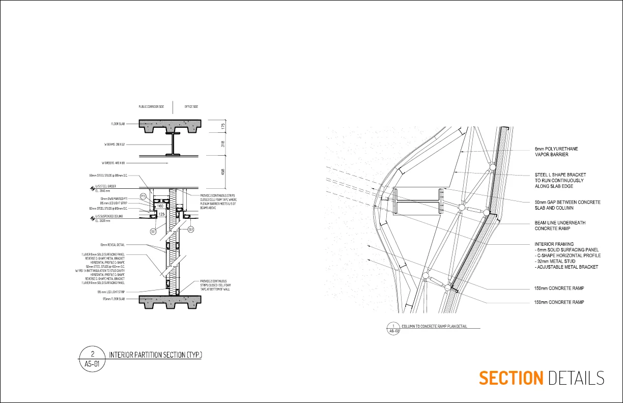
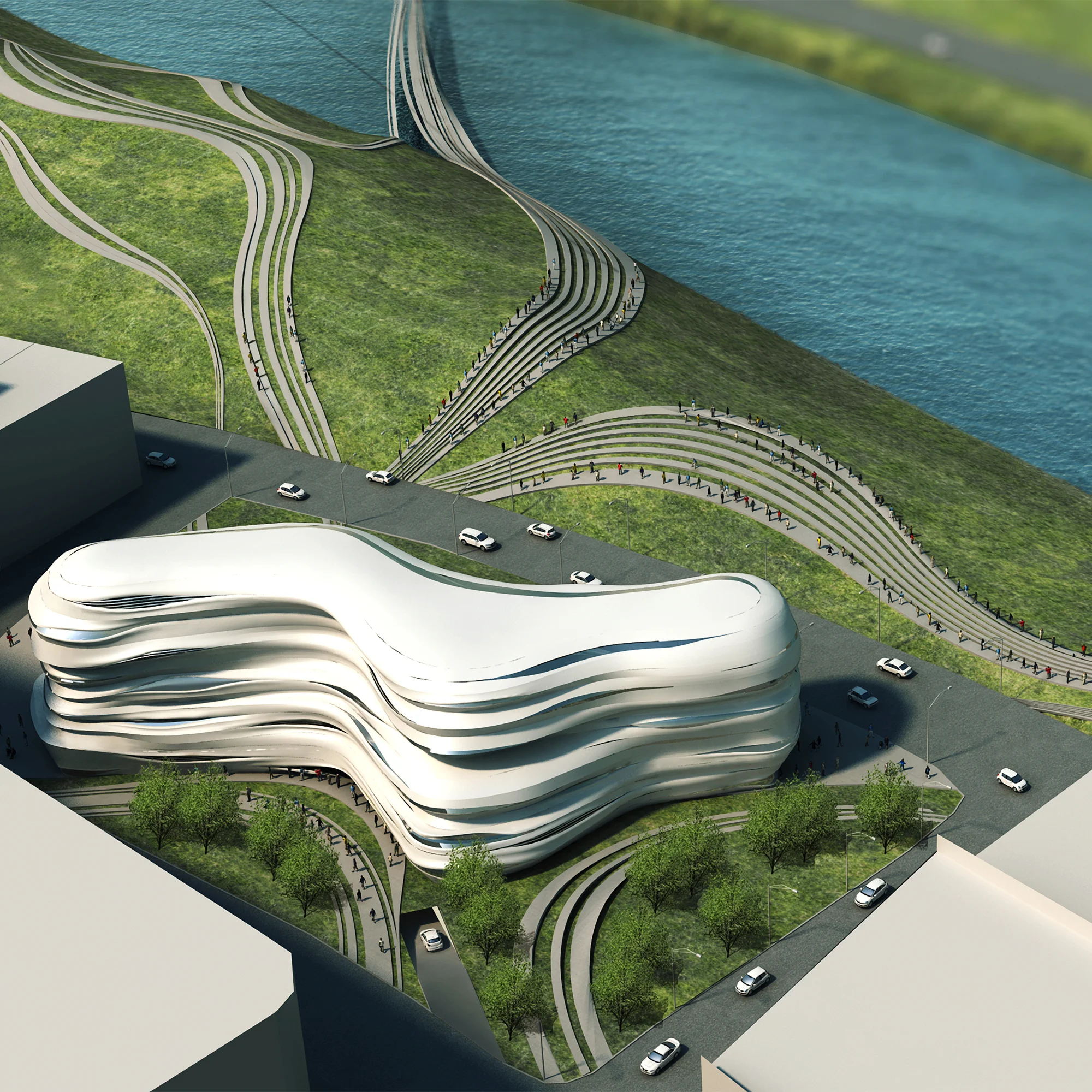
The performative concept of transition in the Yoski Aboriginal Research Institute derived from an in-depth analysis of the existing and proposed West Village site in Calgary, Alberta. Further site investigation revealed an intimate negotiation between predominant dichotomies. The concepts of "hard & soft" and "public & private", in particular, are frequently expressed in the interplay between man-made conditions and the natural landscape. The full integration of the concept into the building systems allowed the idea of transition to be expressed beyond the formal language of the building. A series of performances were generated based on this concept, providing intelligent and sustainable solutions to various design challenges. Special attention was given to the relationship between buildings and the landscape to ensure a smooth gradient throughout the site. The smoothness of the exterior and interior spaces is balanced by the hardness of the primary structure: concrete and steel.
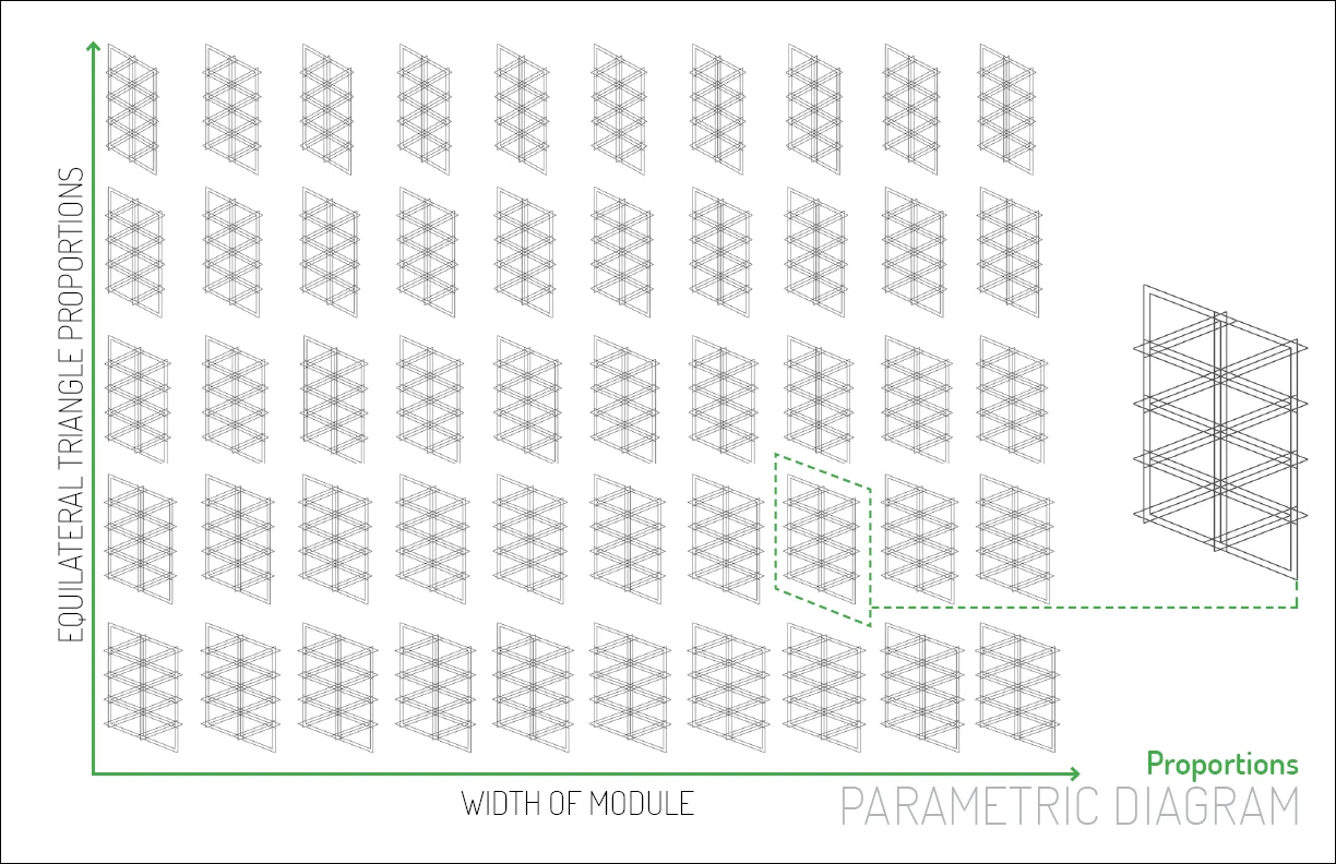
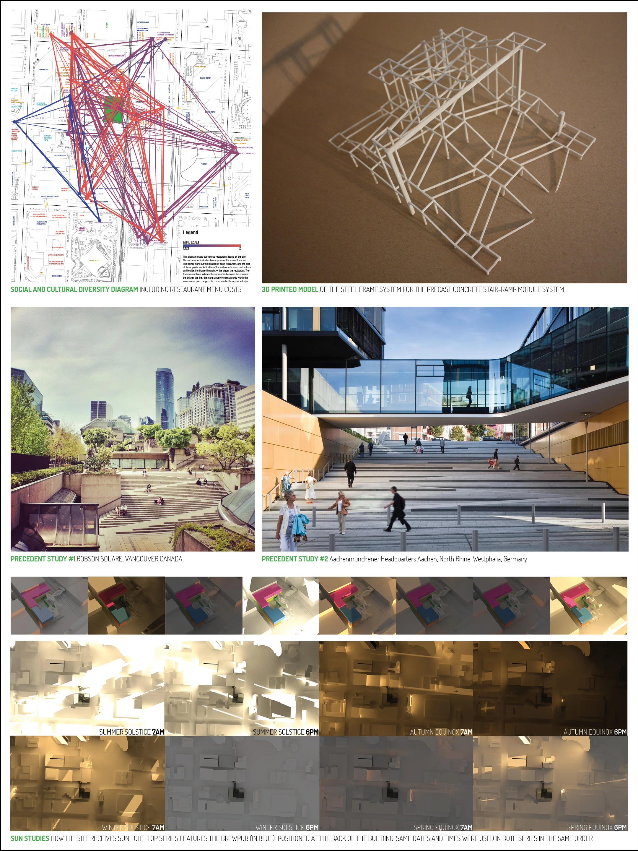
Diagrams are useful tools in driving the design process, capturing ideas beyond the scope of traditional drawings and unveiling relationships that words alone cannot convey.
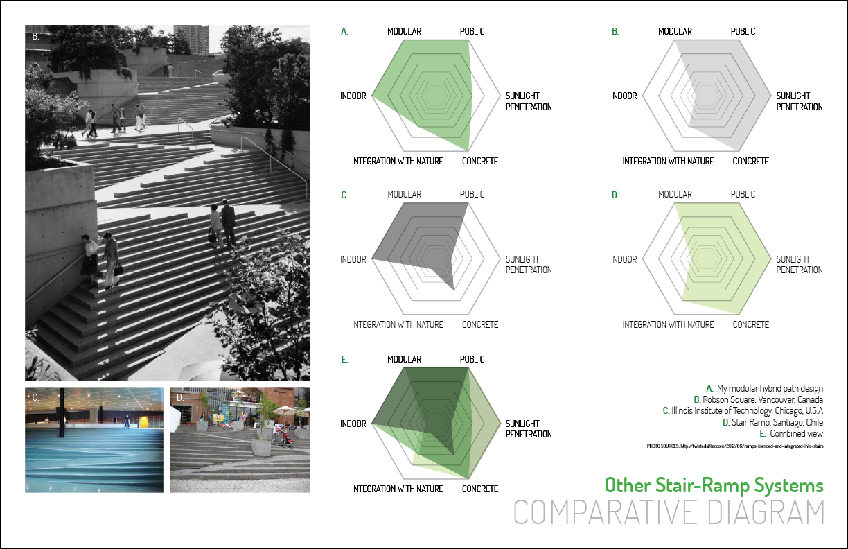
The Hybrid Path, a past completed project, served as the foundation for these retroactive diagrams. Throughout the process, I was able to explore and clarify some of the ideas that weren’t fully communicated in my final project review.
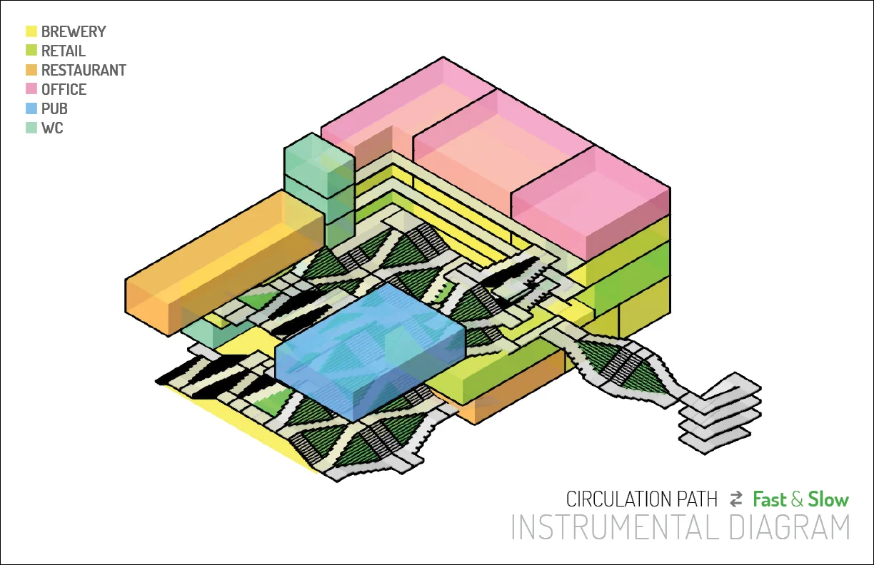
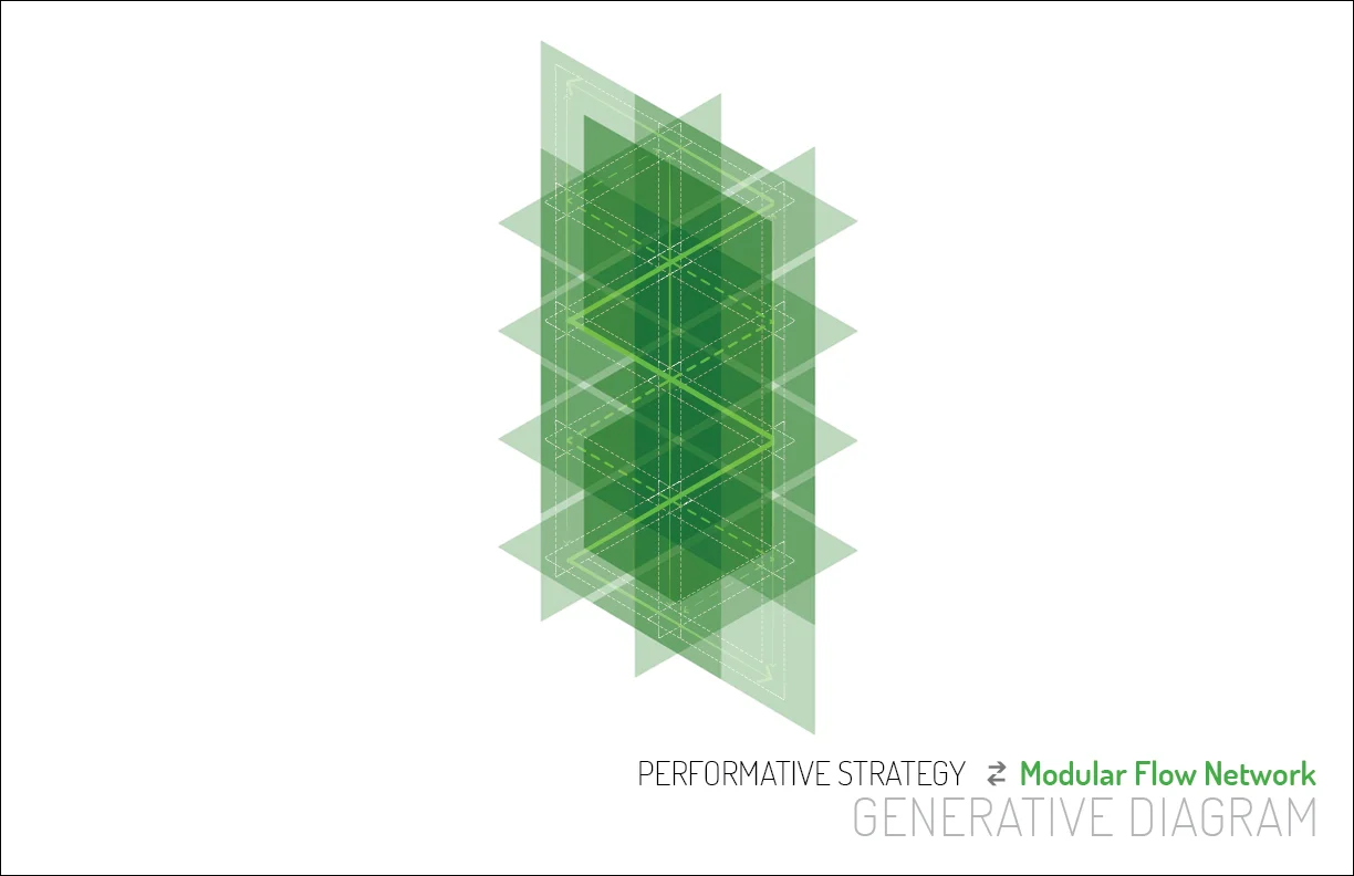
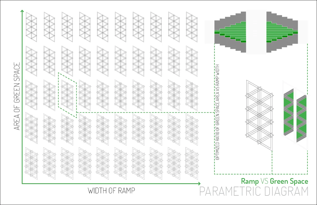
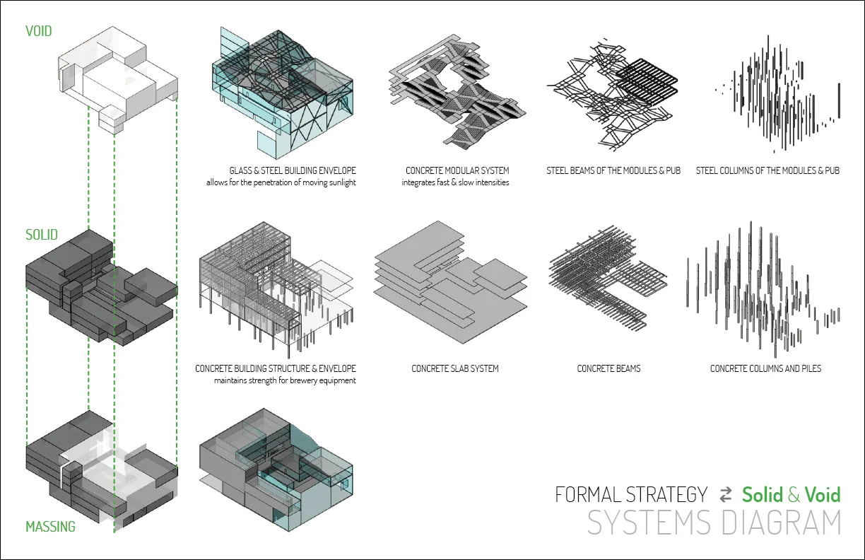
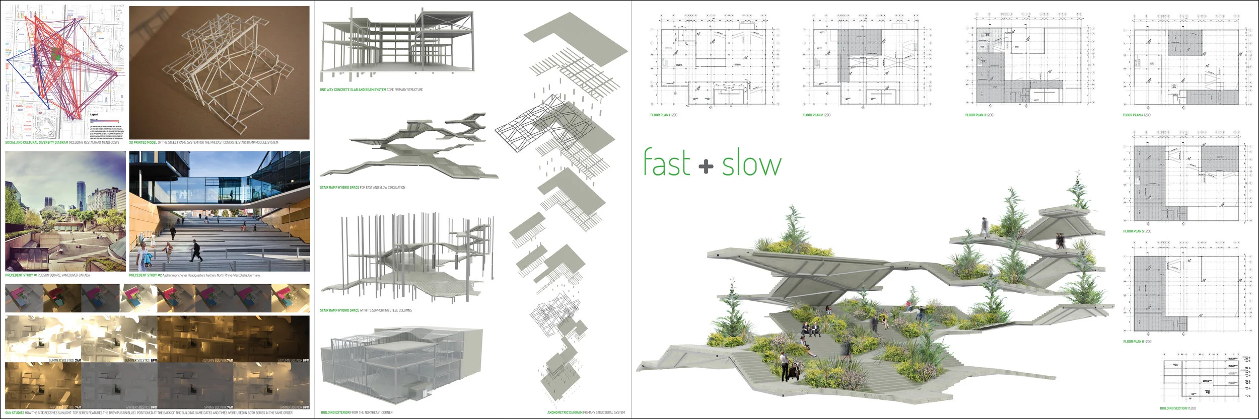
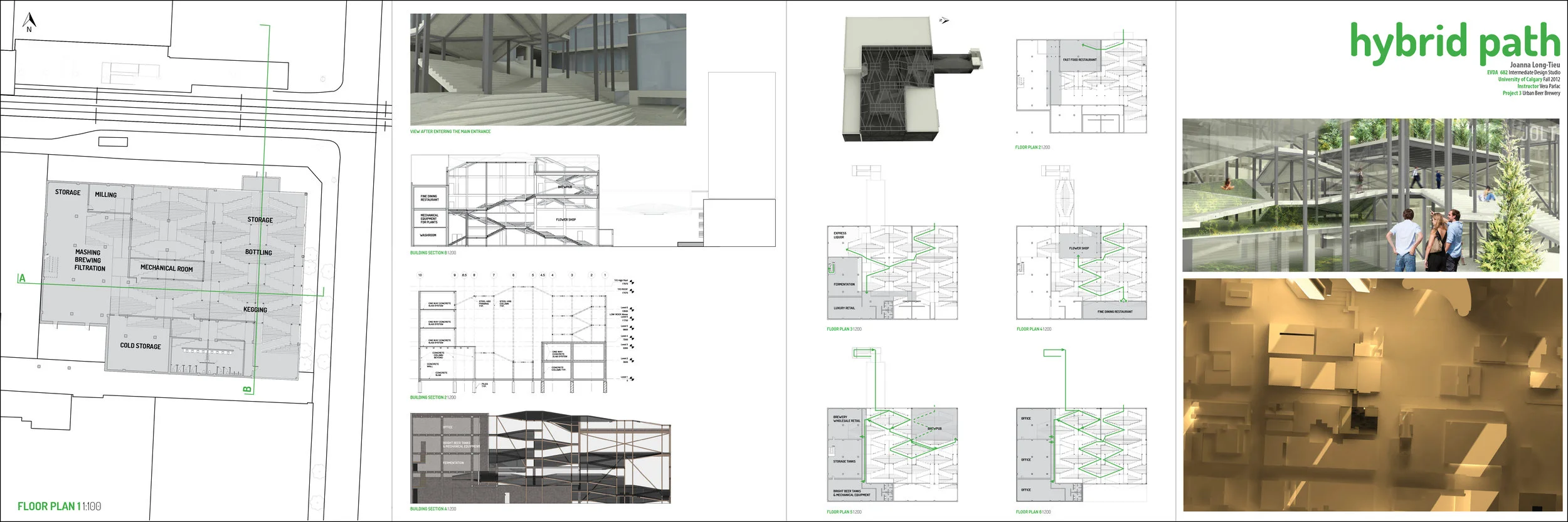
I re-explored the Hybrid Path using the instrumental diagram, time-use diagram, comparative diagram, generative diagram, parametric diagram, and systems diagram.
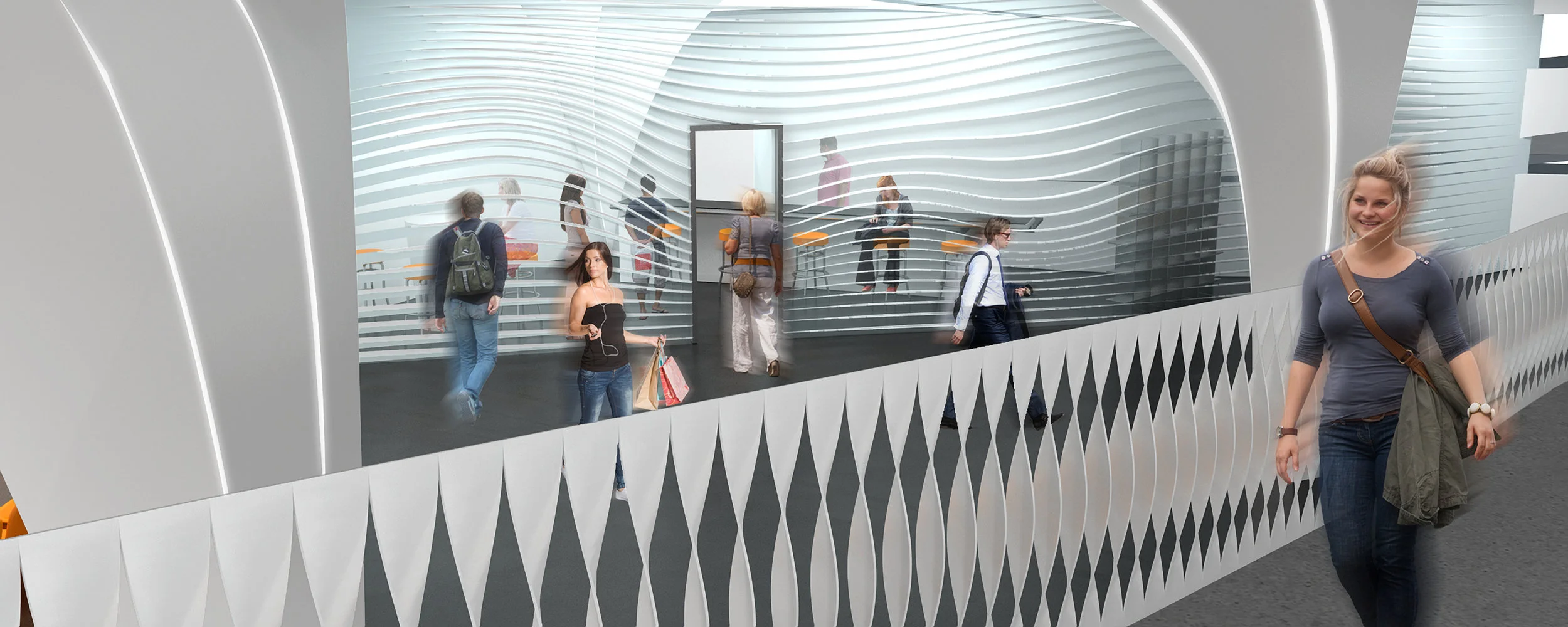
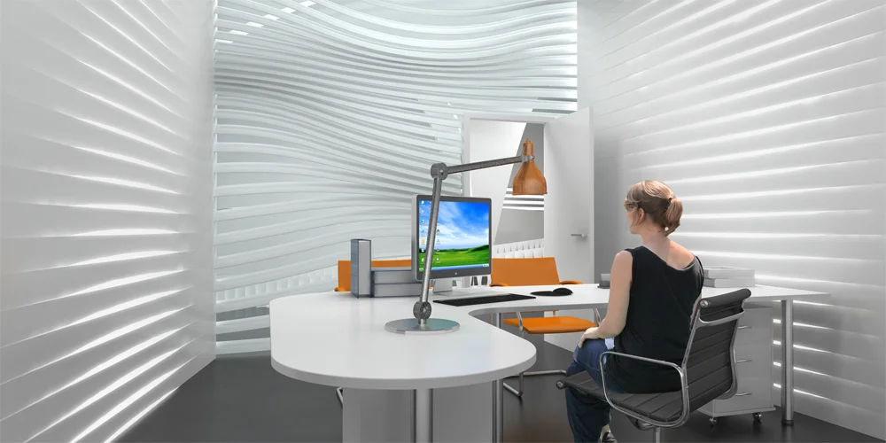
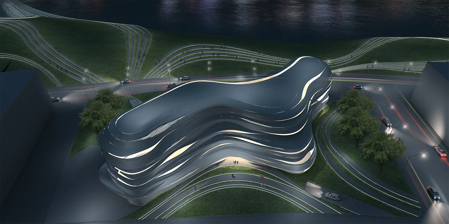
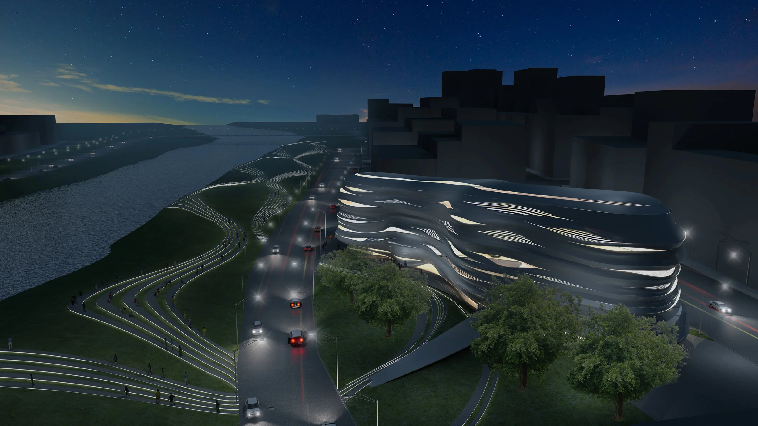
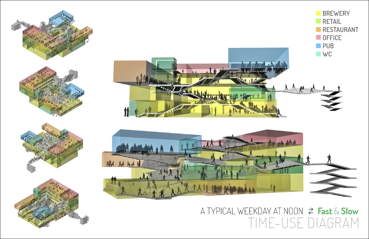
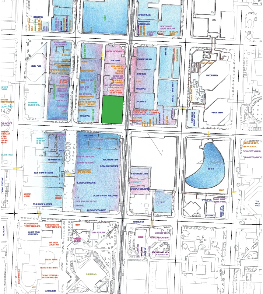
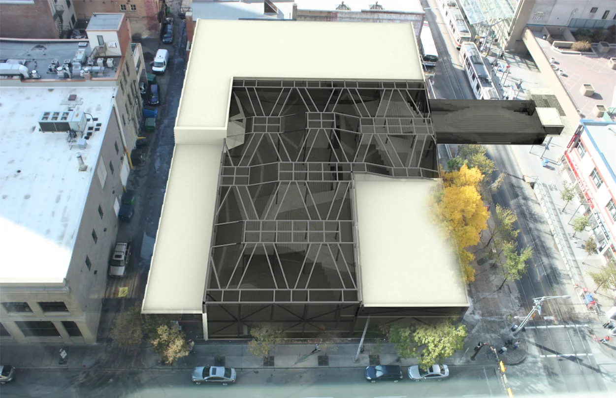
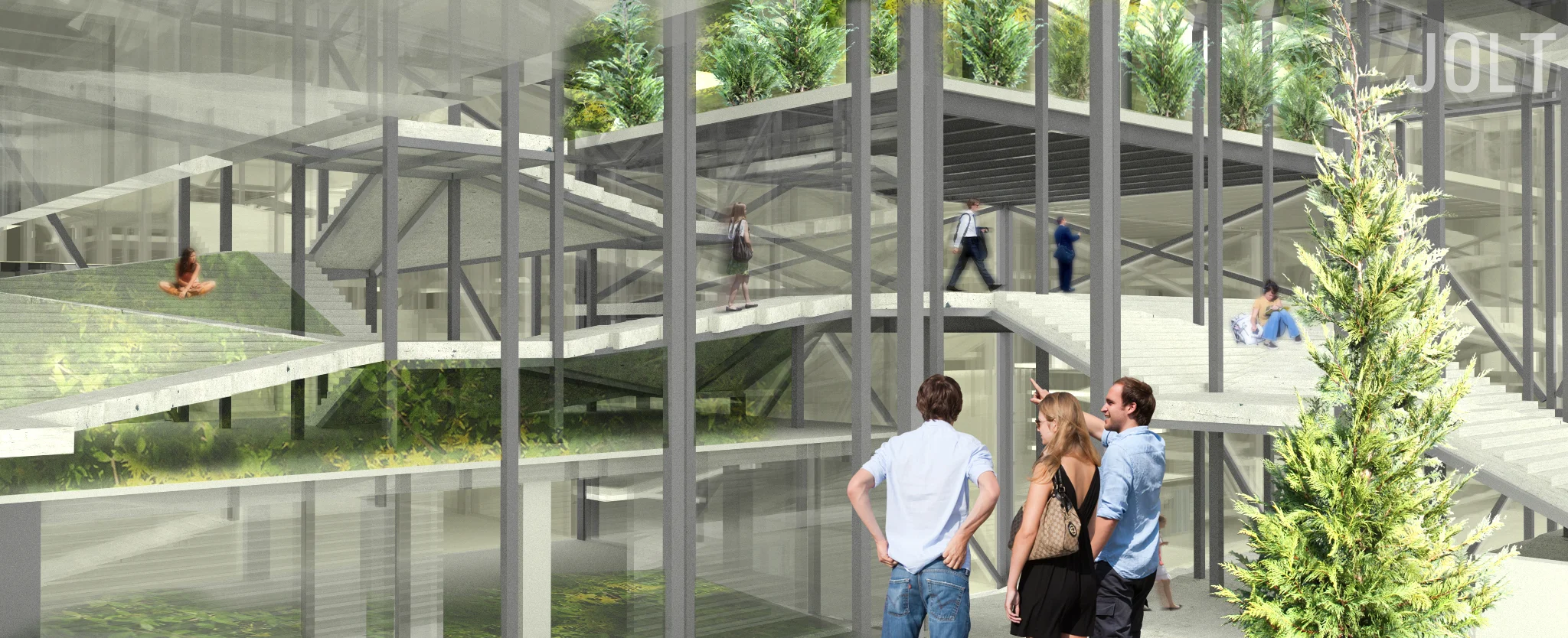
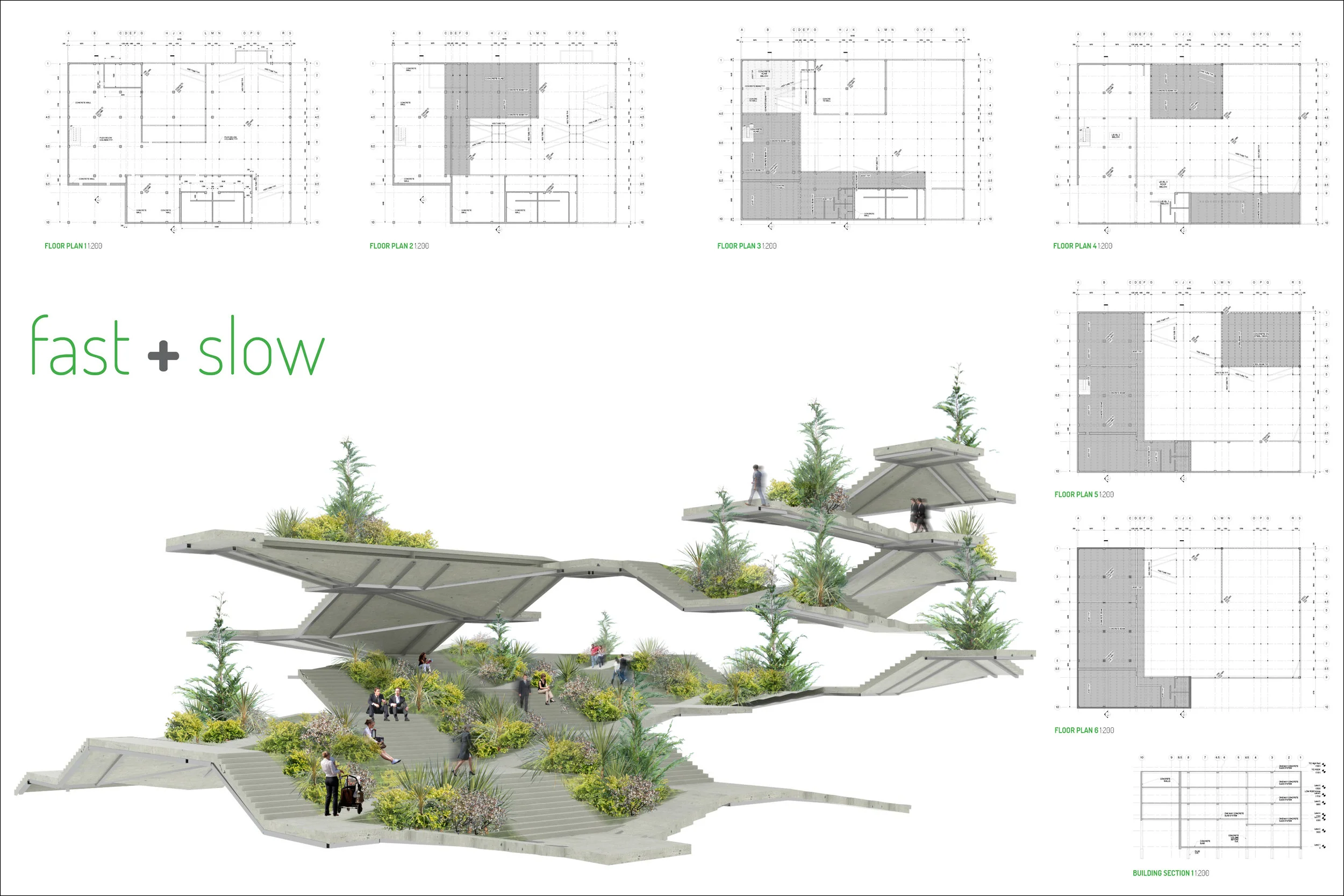
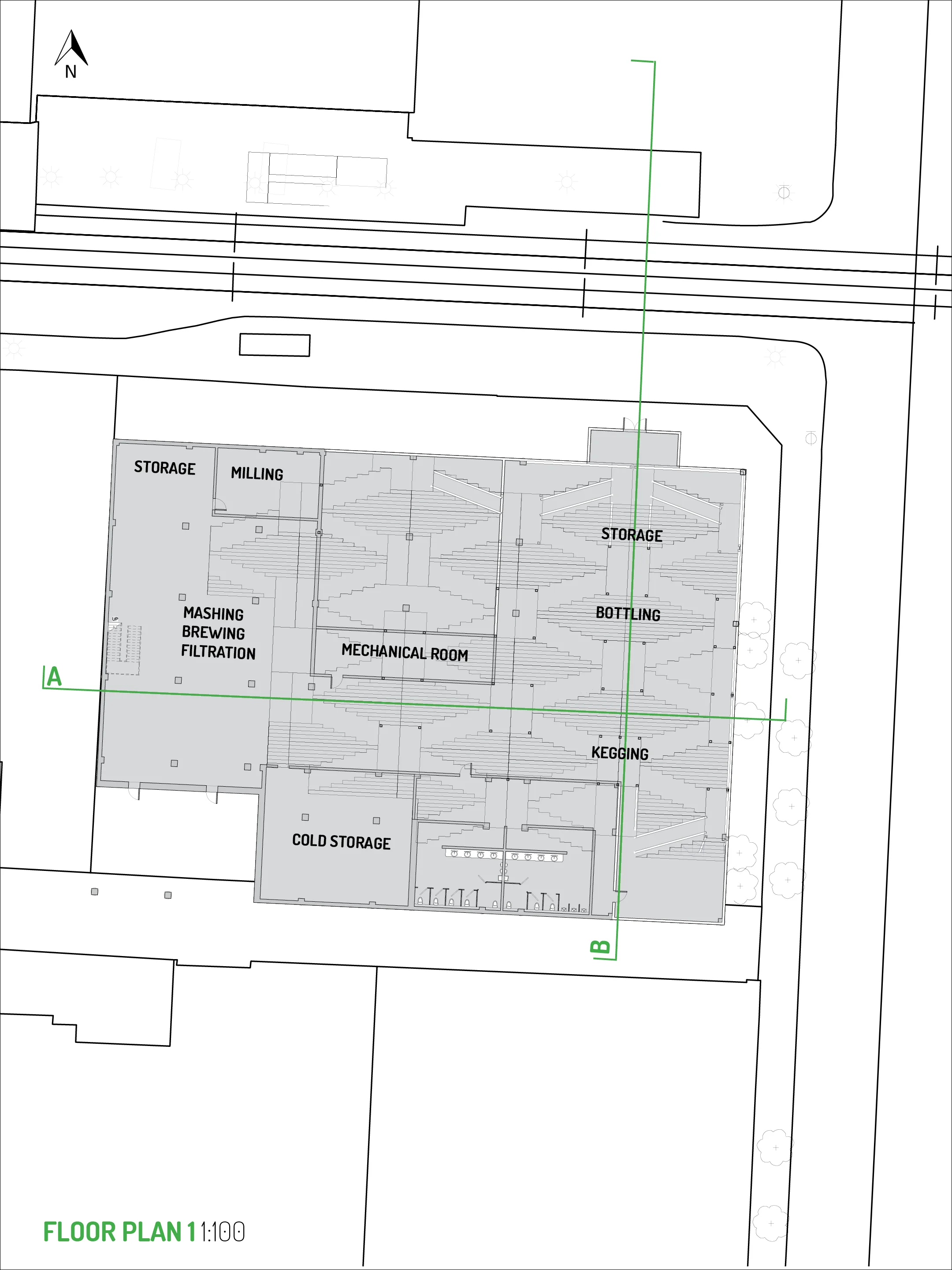
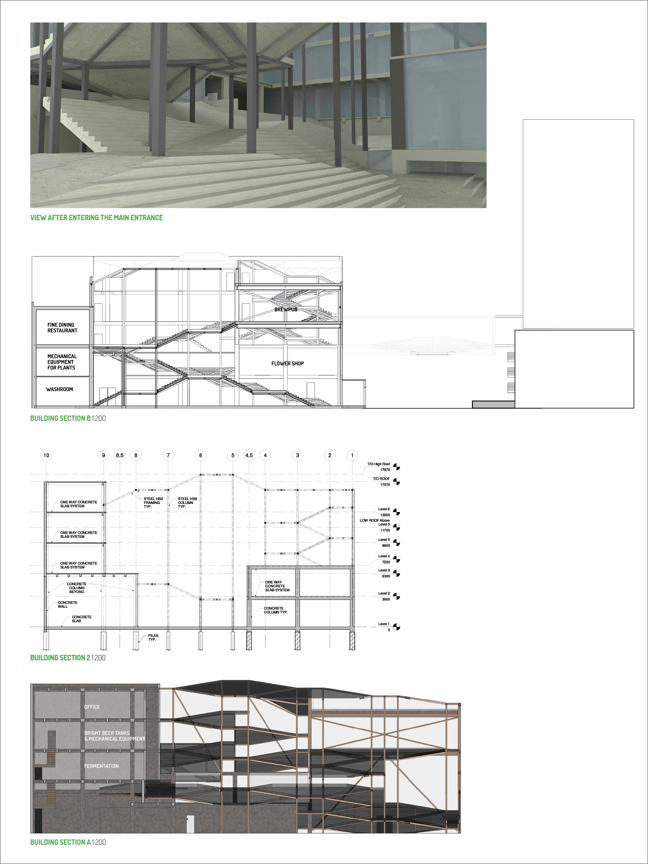
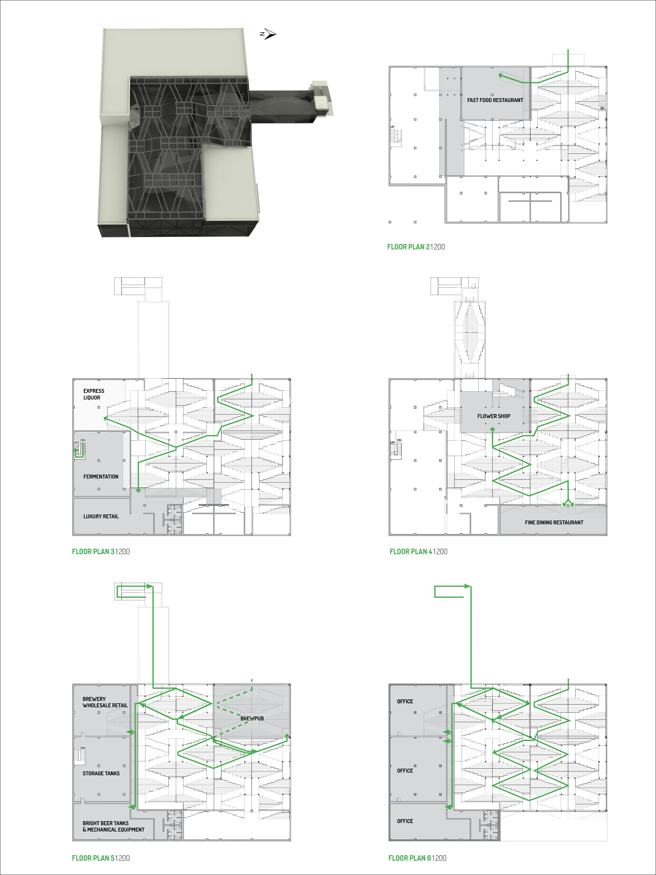
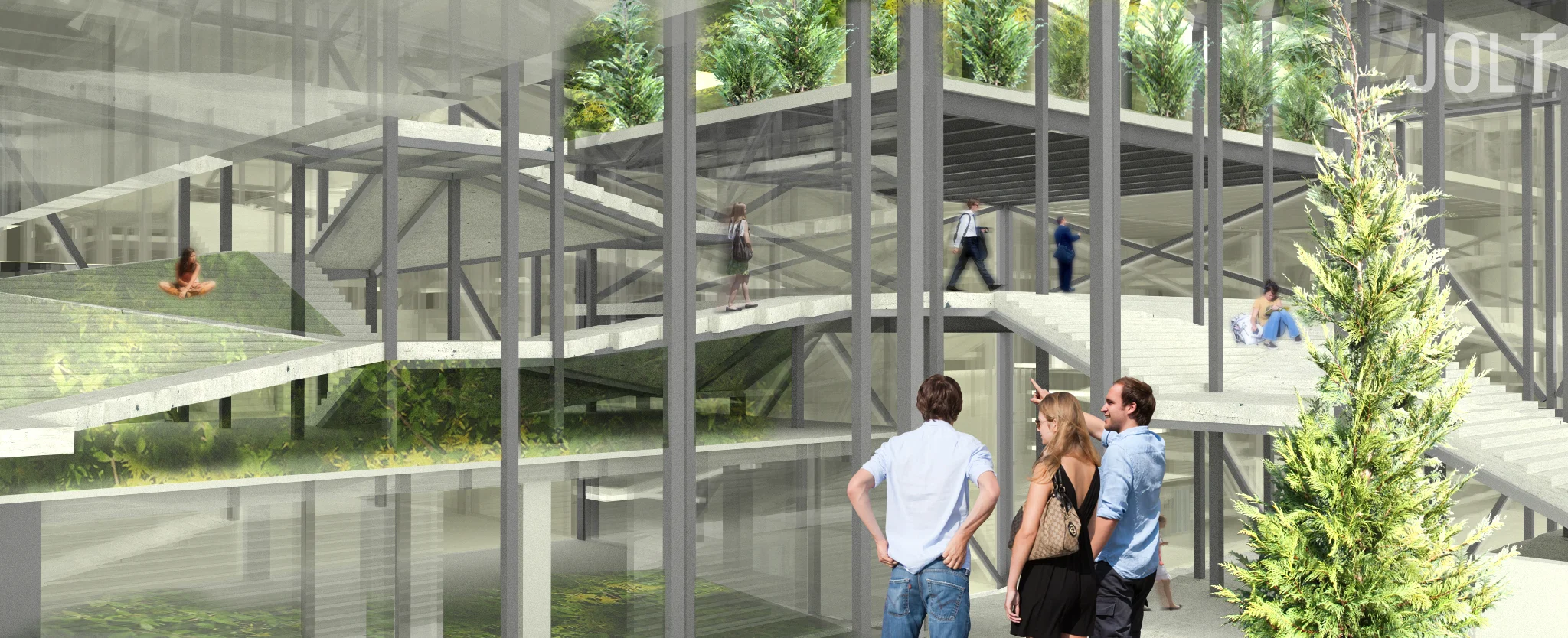
The Hybrid Path was a multi-use building containing a brewery, three retail spaces, three office spaces, two restaurants, and one pub. Located in the intersection of 7th Avenue Southwest and Centre Street, the building was embedded in a site that is characterized by diverse demographics. My building concept was based on speed: the dichotomy of fast and slow applied to many aspects, including the various programs of the building, the movements that take place in downtown, the lifestyle of the users, and the beer production process itself. In order to bring a wide-range of social and cultural groups together, my architectural objective was to create urban fabric based on fast and slow movements through space.
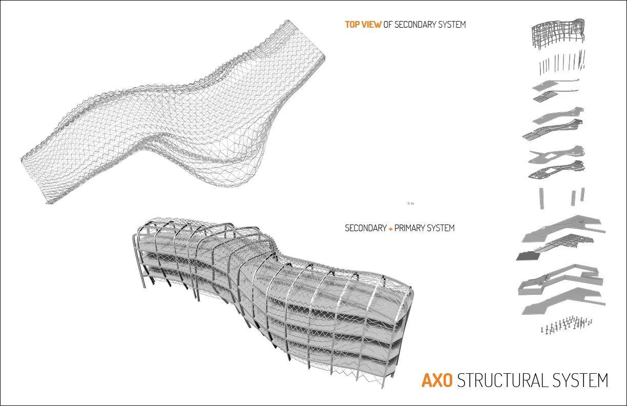
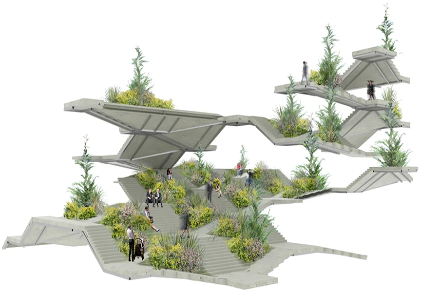
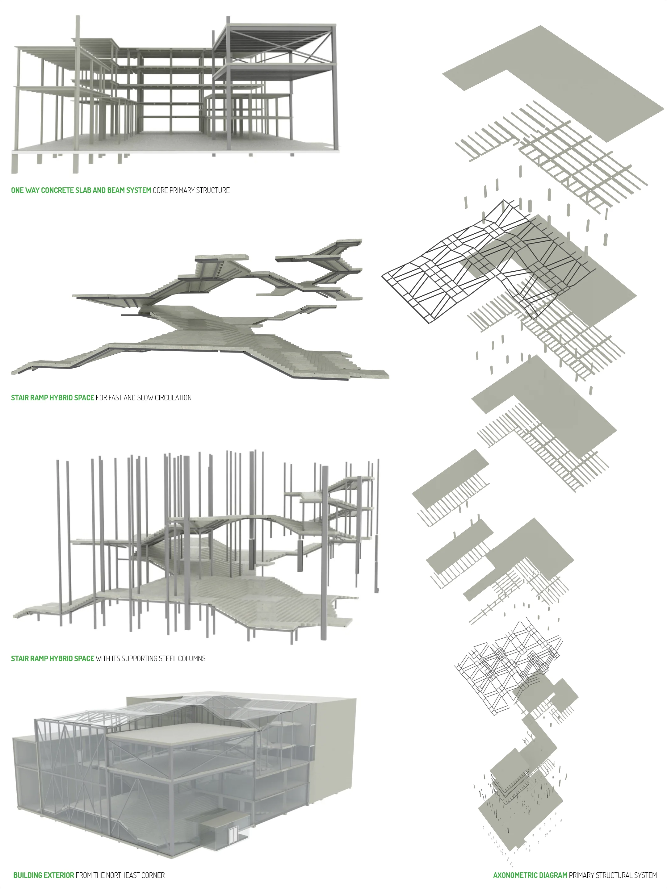
This was implemented through a complex stair-ramp assembly constructed out of steel framing as its primary structural system to act as the main circulation space. The dynamism of this intricate system was intended to juxtapose with the regularity of the other main primary structural system—a one-way slab and beam system. Because the stair-ramp assembly tied into various levels of the building, its structural integrity heavily depended on the durability of the main concrete structural system. In the end, the two distinct systems worked together to embody the environment of fast and slow processes.
The one-way slab and beam system was chosen for the main solid core of the building for several reasons. First of all, the floor plates had a rectangular shape that was uniform across several levels; it could therefore follow a regular orthogonal column grid and easily accommodate floor penetrations across the beam line. With the slab spanning exclusively in the short direction, there was a clear indication of which direction it was spanning. The columns were parallel to each other in one direction, and everything lined up accordingly; it was easy to determine which way the load was being transmitted. The beams and joists were evenly spaced and they were all lead to the columns to ensure that the load was transmitted properly. Secondly, the continuous one-way slabs were post-tensioned to reduce its overall depth and dead load; the slabs across all levels had a consistent thickness of 100mm. The beams underneath were greater in depth, however, there was a lot of mechanical equipment within the brewery that could utilize the void space between beams to run ducts and electrical work.
Another reason why a cast in place concrete system was chosen is that its mass allowed the building to be quiet and stable. Because the building was multi-use, it was crucial that the performance of beer production did not transmit noise or vibrations to areas that required silent and stable environments. Next, cast in place concrete systems are strong, and the slab thicknesses were sufficient to satisfy fire-rating requirements. In order to ensure the strength of the foundation, the structure was underpinned with piles (lined up with the columns) in areas located away from the two concrete load-bearing walls in the southwest of the building. The 500mm thick load-bearing walls are positioned in the corner of the building that extended to all levels of the brewery, which tended to be the areas that needed to support a heavier load. It was also a good spot for the load-bearing walls as no natural light needed to come into those spaces.
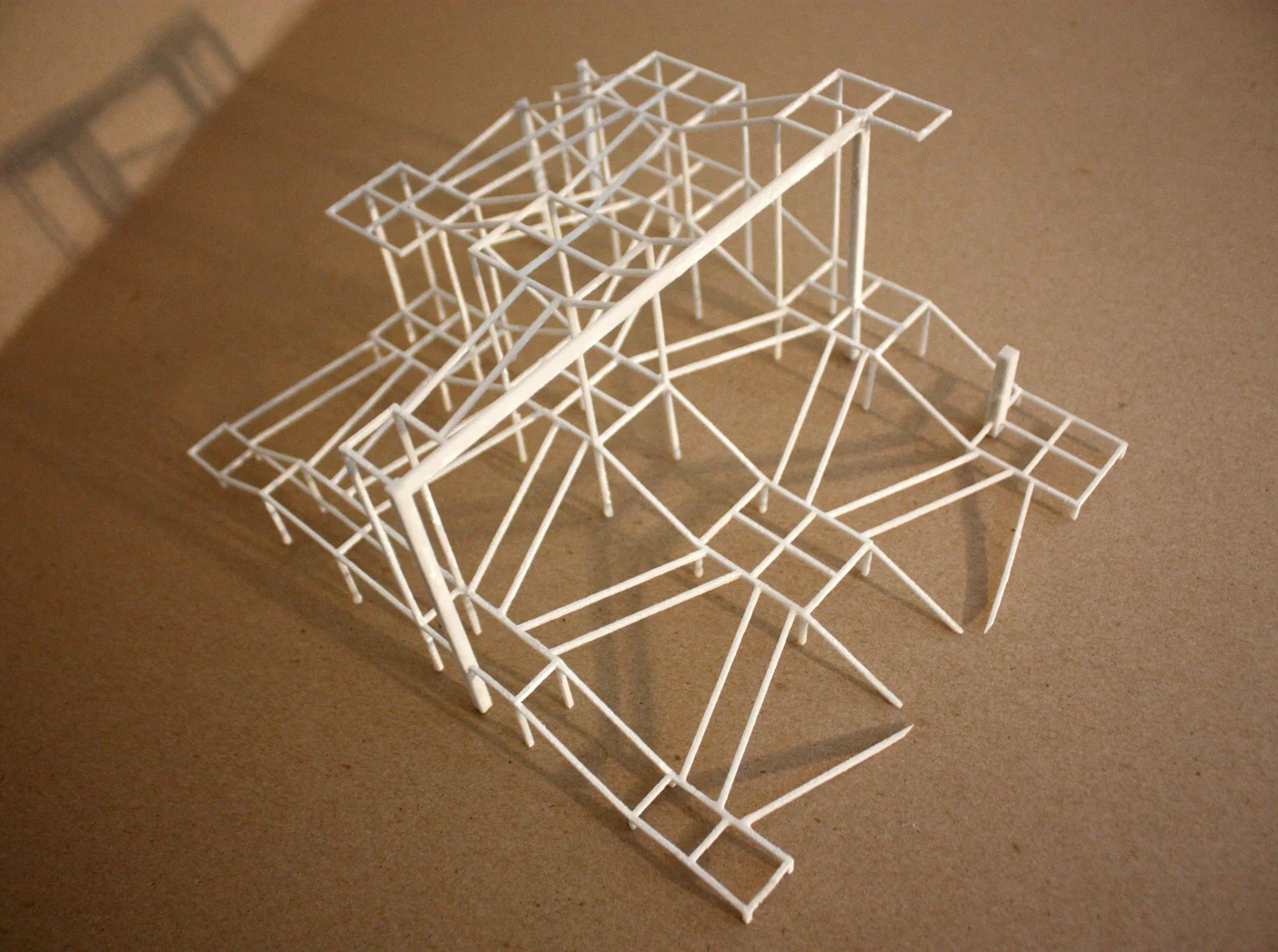
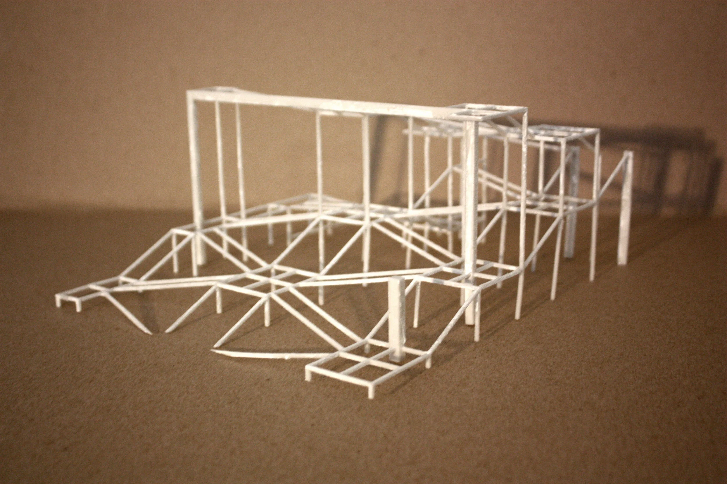
The steel framing system was comprised of prefabricated parts that were welded together to form a framework for the modular stair-ramp system. While custom fabrication can be quite expensive, the repetitive nature of the assembly should reduce the overall cost. This primary structural system used HSS tubes with HSS columns to hold up precast concrete slabs that made-up the stair-ramps. The stair-ramps acted as circulation for the building, so there was a lot of walking that would occur on its surface. Besides the fact that it was readily-available, the use of concrete for the slabs was therefore a suitable material because of its acoustic properties and ability to absorb vibrations. Because it was a precast form, the construction process would be quick to fabricate in the production plant—one standard mold would be created and then multiple forms would be poured and casted in a repeated process. Upon site arrival, the assembly process would be quick since no concrete formwork was needed. The use of concrete for the stair-ramp system also aligned with the architectural aims of integrating the two distinct primary structural systems together.
Next, steel was used for the framing of this system due to its great strength and mechanical properties. Besides its ability to bend into unique shapes, steel was not bulky and did not take up a large amount of mass to perform as intended. The use of steel offered a safety and robust system that met the architectural objectives of a system that appeared to be lightweight and dynamic. Another reason why steel was suitable for this system was that it offered sufficient warning before its material failure. Should failure occur in an area within the system, there would be ready-made prefabricated parts that could easily replace the damaged parts.
The two primary structural systems of the Hybrid Path were created to meet the architectural aims of the project, with the depiction of the idea that systems of a dichotomous nature, whether physical or social, could interact to form an integrated system that worked both functionally and aesthetically.
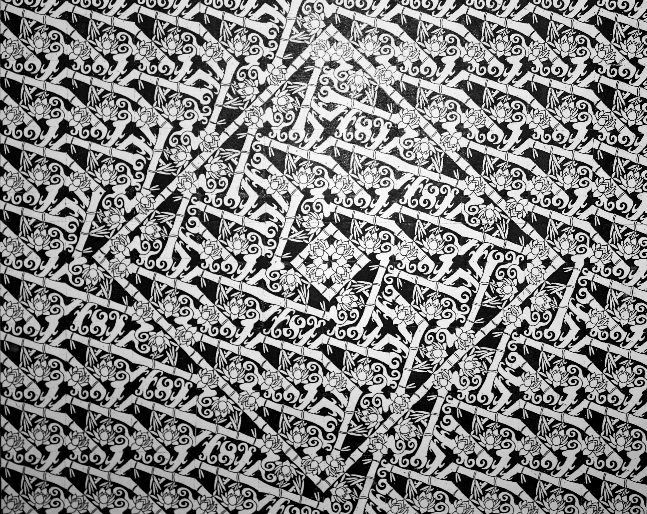
PATTERN #1: DIAMOND-CUT
Systematic tile designs of one style were assembled to create a diamond pattern in the central part of the composition.
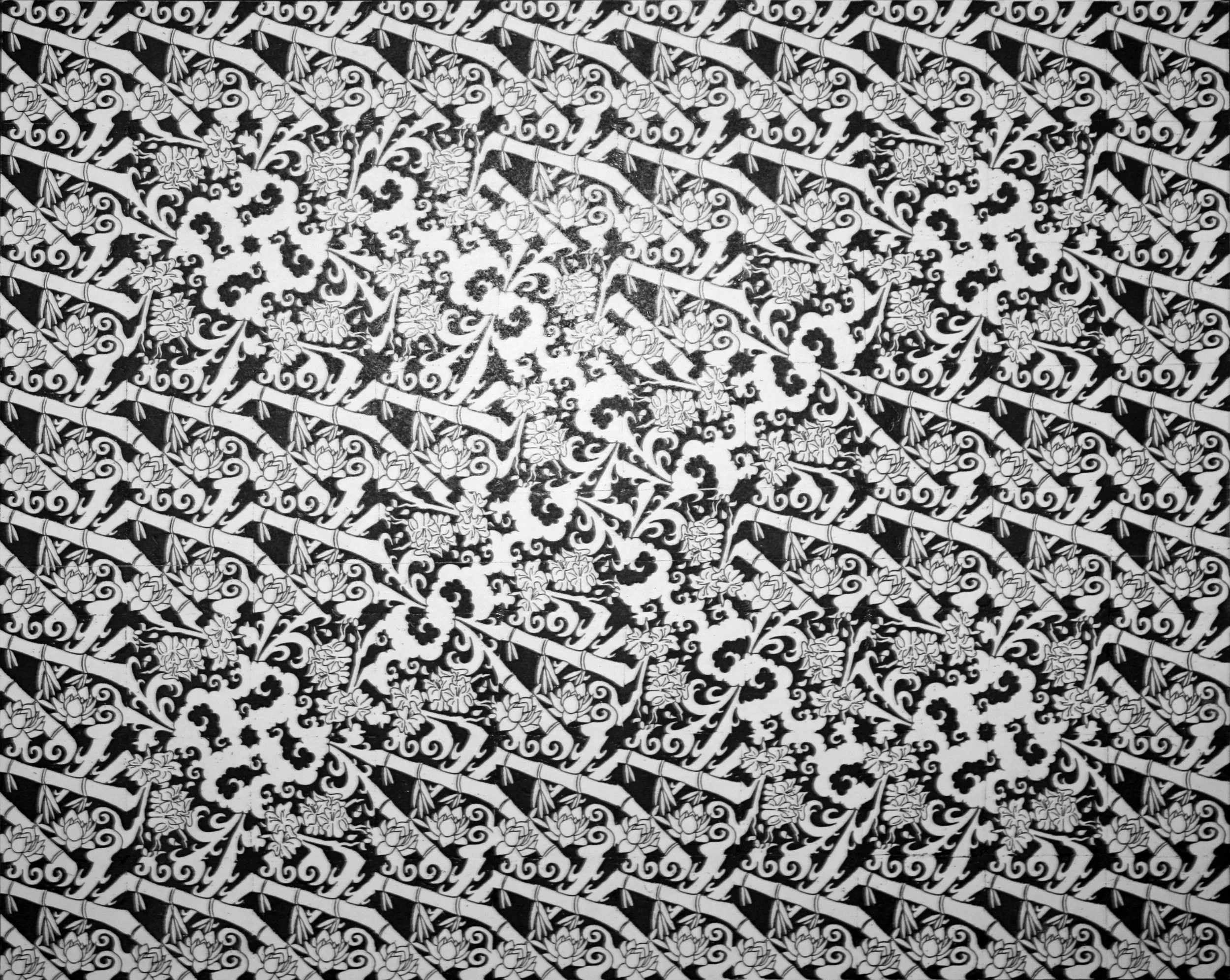
PATTERN #2: 'X' MARKS THE SPOT
Systematic tile designs of two different styles were assembled to create an Italic 'X' in the central part of the composition.
Tile Designs:
Lotus and Bamboo (Left)
Cherry Blossom and Clouds (Right)
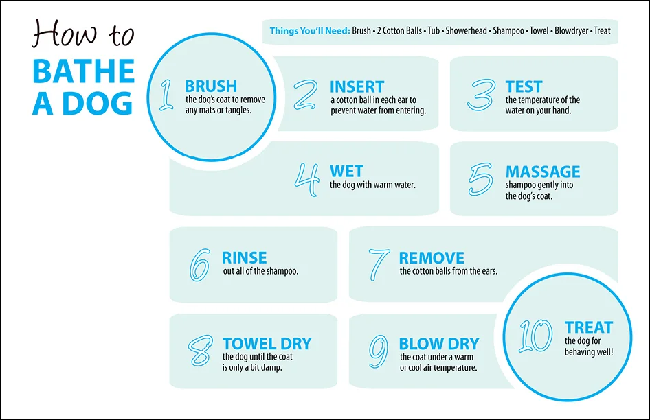
Diagram #1: HOW TO BATHE A DOG
Instructional sequencing using image, word, and image+word formats
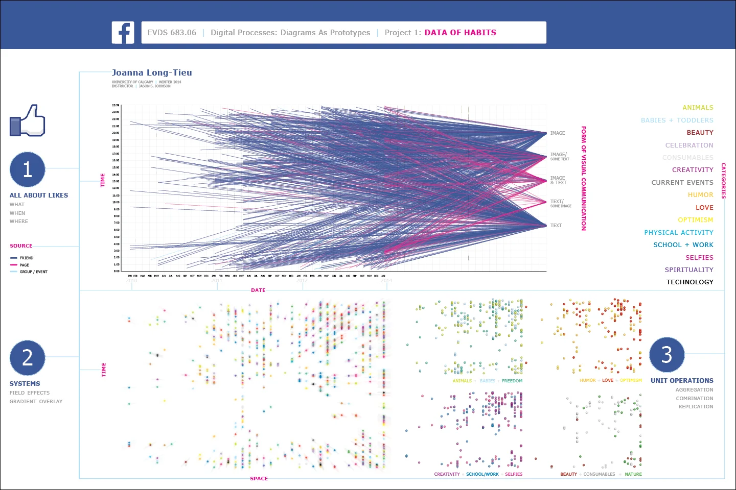
Diagram #2: FACEBOOK ADDICTION
This Personal Data Cloud diagram investigates space/time relationships embedded in digital devices and personal networks. Relationships were explored between multiple characteristics of singular pieces of information: Facebook 'likes'.
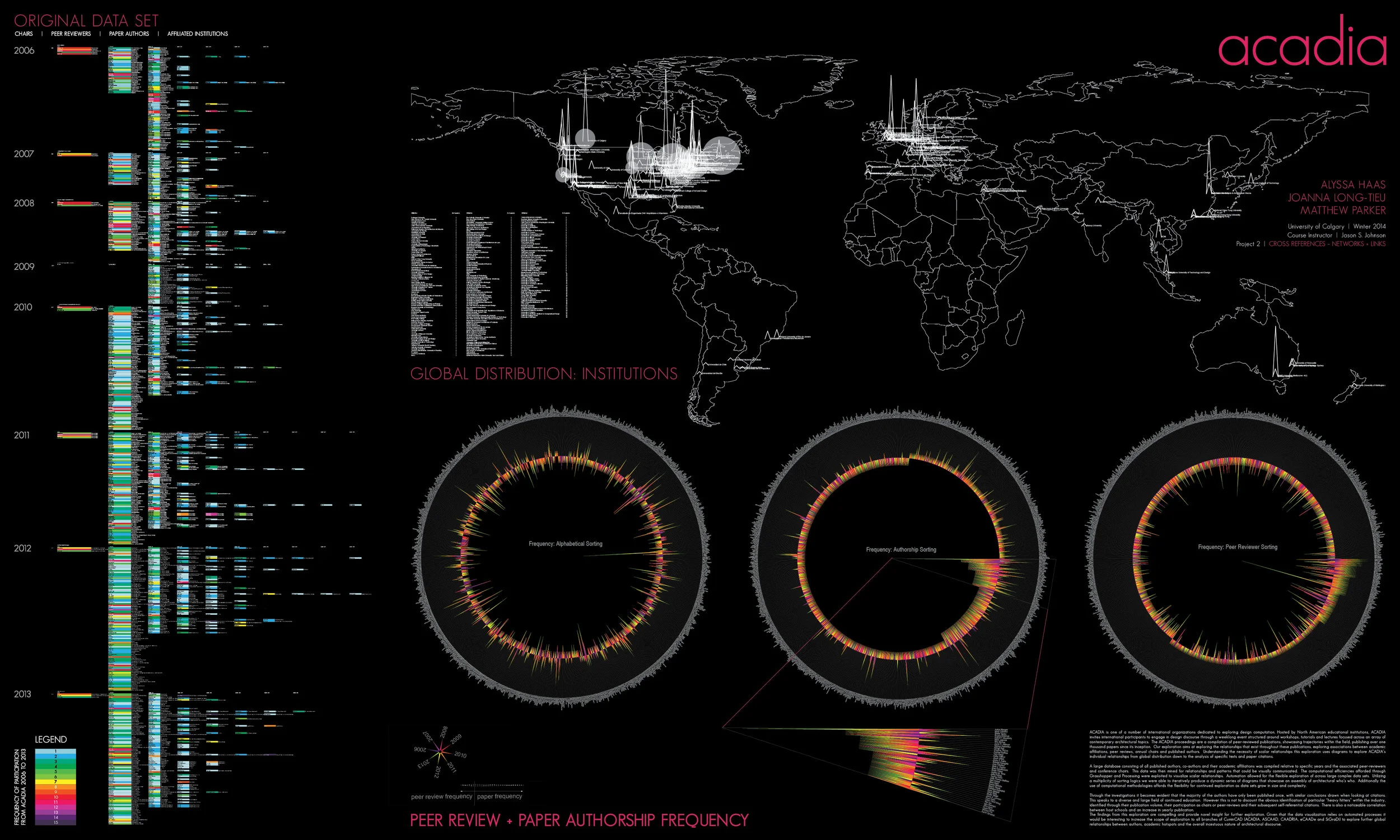
Diagram #3: ACADIA
ACADIA is one of a number of international organizations dedicated to exploring design computation. Hosted by North American educational institutions, ACADIA invites international participants to engage in design discourse through a weeklong event structured around workshops, tutorials and lectures focused across an array of contemporary architectural topics. The ACADIA proceedings are a compilation of peer-reviewed publications, showcasing trajectories within the field, publishing over one thousand papers since its inception. In this group project, our exploration aims at exploring the relationships that exist throughout these publications, exploring associations between academic affiliations, peer reviews, annual chairs and published authors. Understanding the necessity of scalar relationships this exploration uses diagrams to explore ACADIA’s individual relationships from global distribution down to the analysis of specific texts and paper citations.
A large database consisting of all published authors, co-authors and their academic affiliations was compiled relative to specific years and the associated peer-reviewers and conference chairs. This data was then mined for relationships and patterns that could be visually communicated. The computational efficiencies afforded through Grasshopper and Processing were exploited to visualize scalar relationships. Automation allowed for the flexible exploration of across large complex data sets. Utilizing a multiplicity of sorting logics we were able to iteratively produce a dynamic series of diagrams that showcase an assembly of architectural who’s who. Additionally the use of computational methodologies affords the flexibility for continued exploration as data sets grow in size and complexity.
Through the investigations it becomes evident that the majority of the authors have only been published once, with similar conclusions drawn when looking at citations. This speaks to a diverse and large field of continued education. However this is not to discount the obvious identification of particular “heavy hitters” within the industry, identified through their publication volume, their participation as chairs or peer-reviews and their subsequent self-referential citations. There is also a noticeable correlation between host schools and an increase in yearly publication.
The findings from this exploration are compelling and provide novel insight for further exploration. Given that the data visualization relies on automated processes it would be interesting to increase the scope of exploration to all branches of CuminCAD (ACADIA, ASCAAD, CAADRIA, eCAADe and SiGraDi) to explore further global relationships between authors, academic hotspots and the overall incestuous nature of architectural discourse.
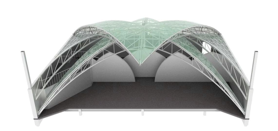
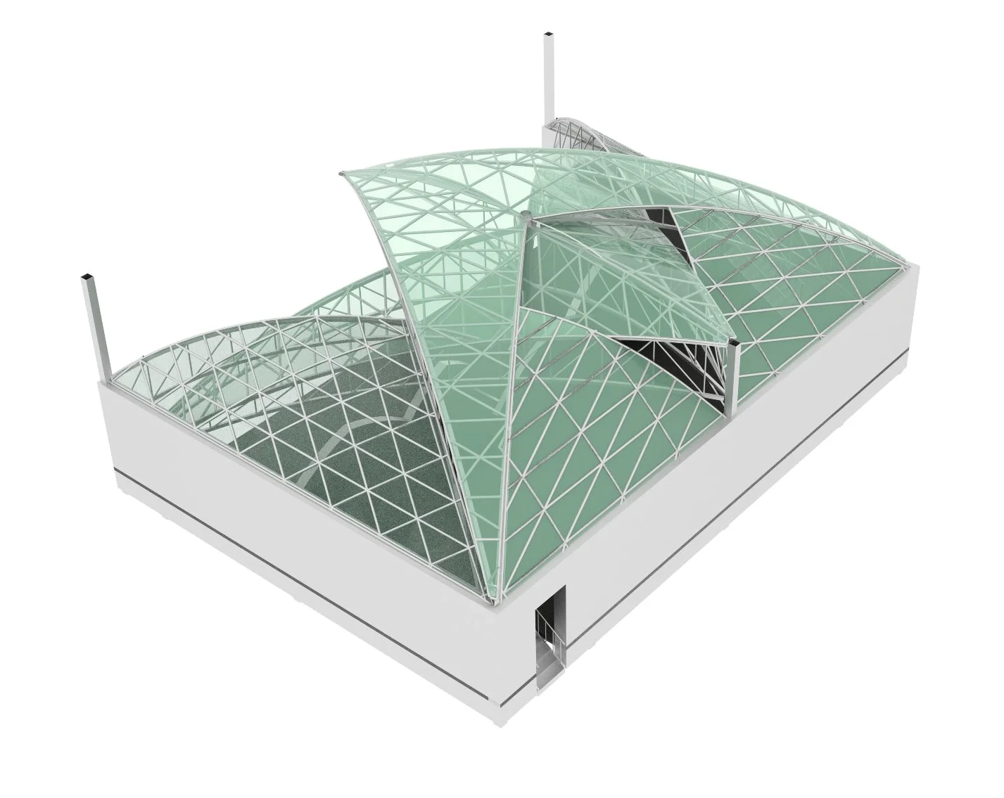
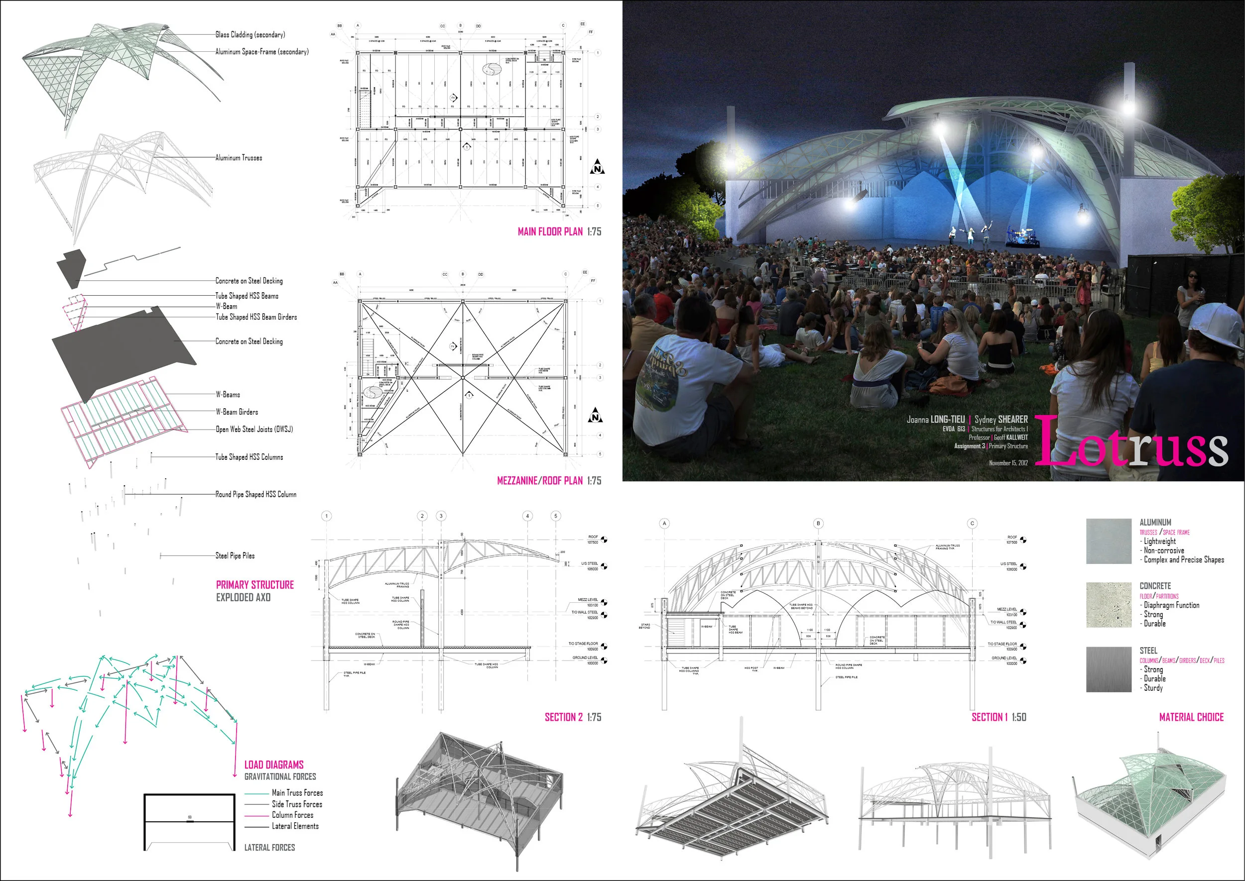
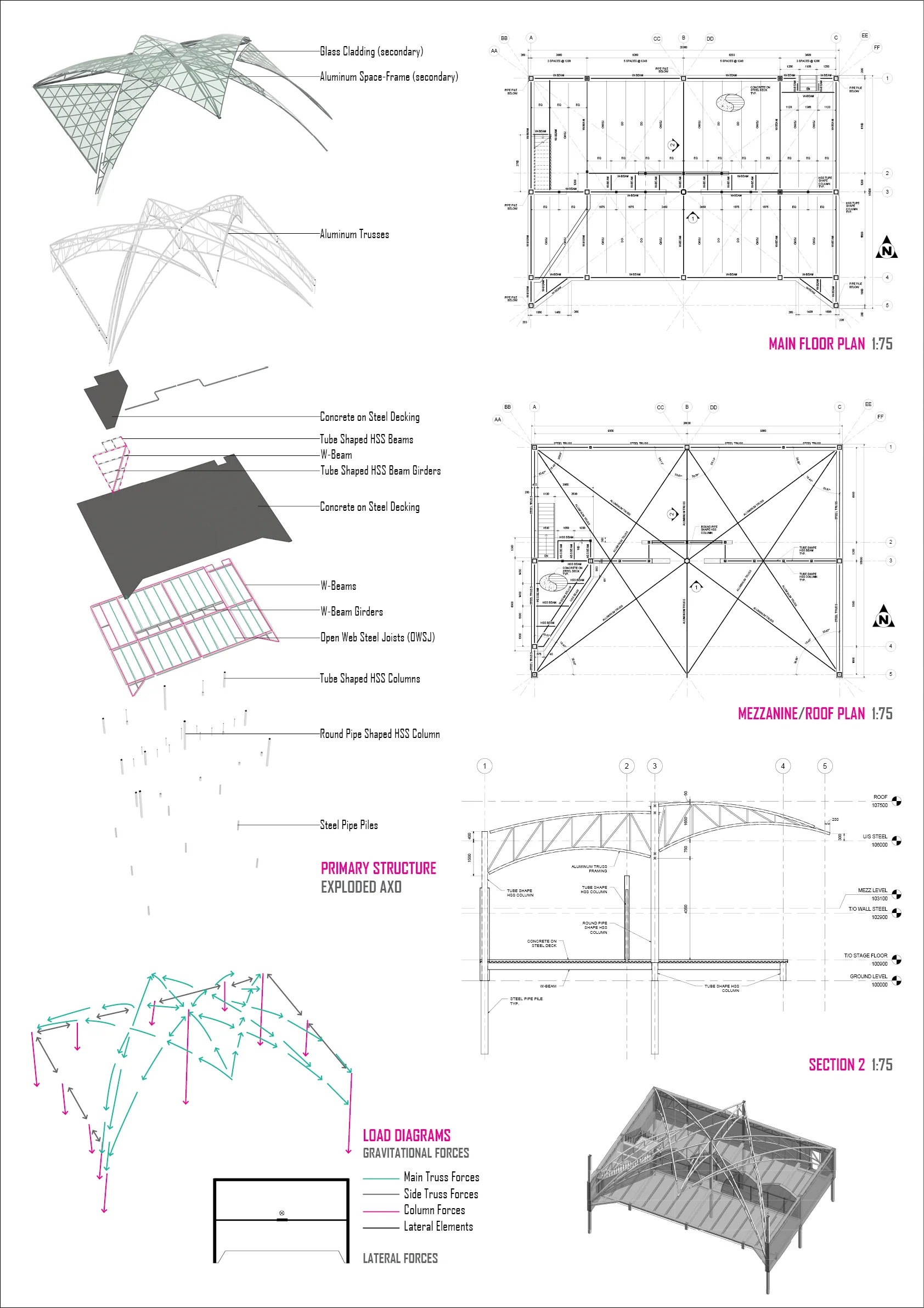
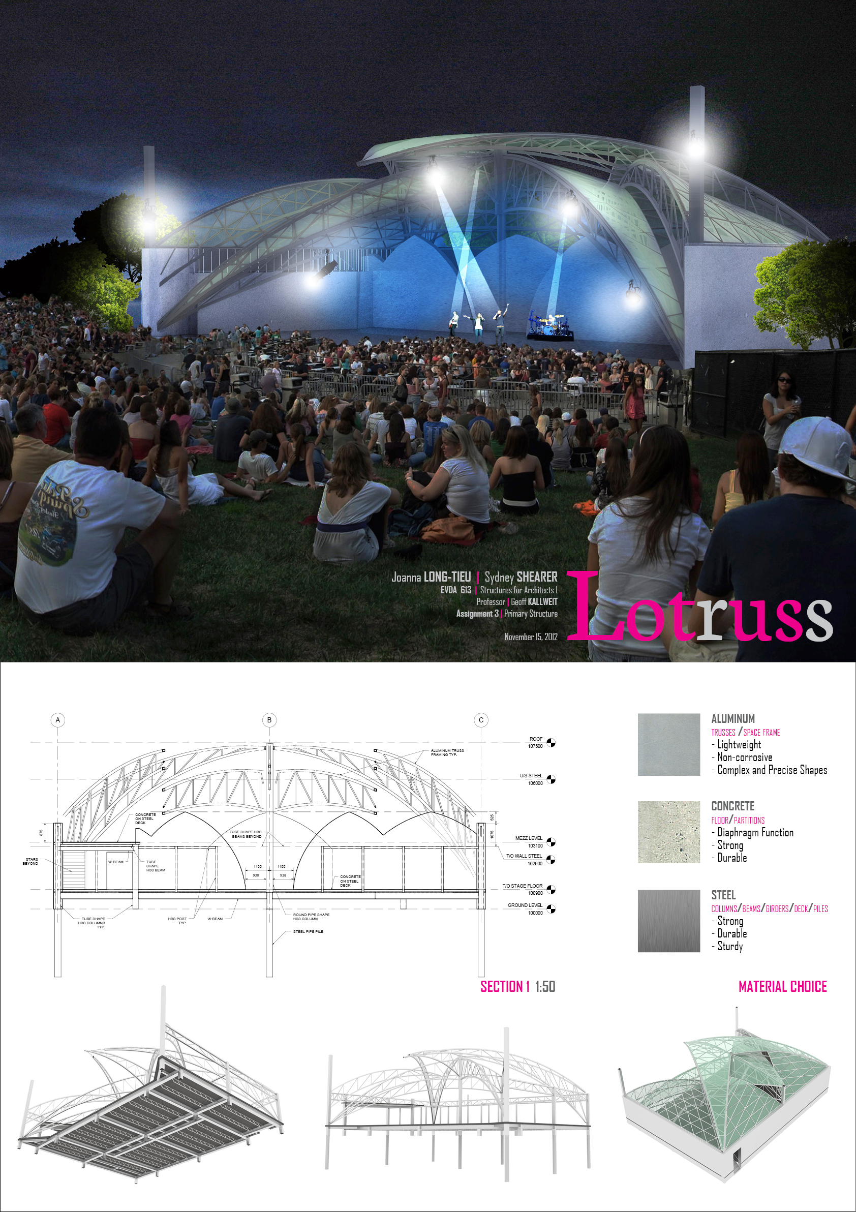
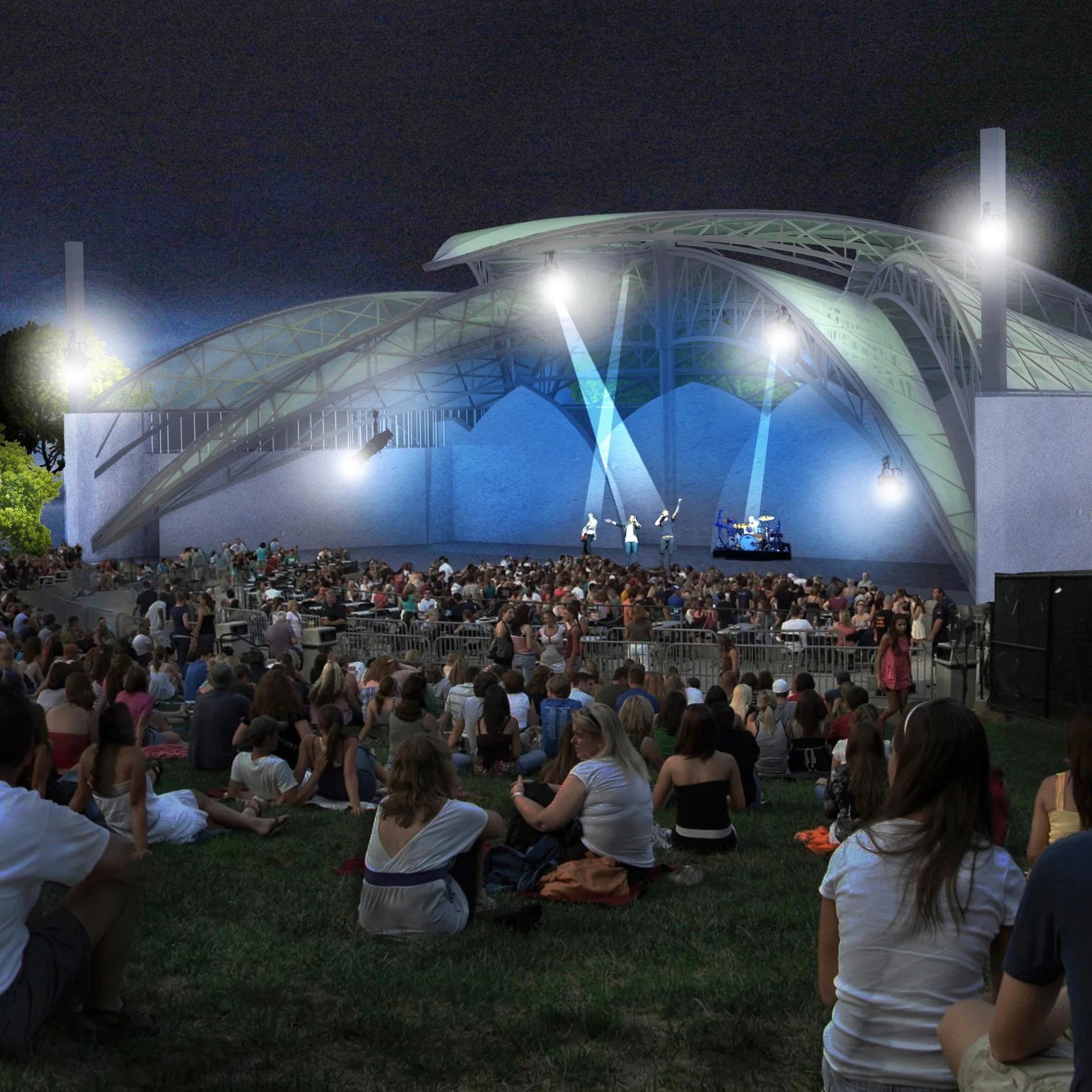
Lotruss was designed conceptually and mathematically as an outdoor stage. The conceptualization of a lotus-shaped roof needed to follow dimensional and material constraints, as well as the following performative aspects:
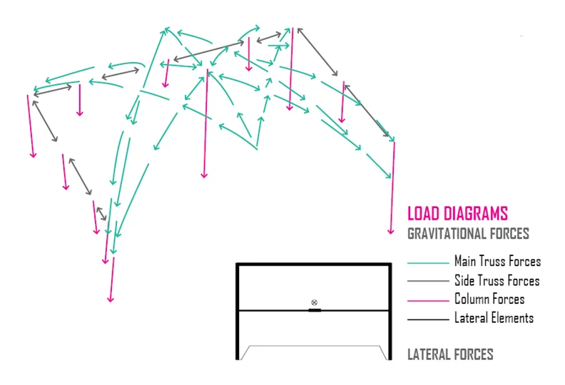
- gravitational forces (main truss forces, side truss forces, column forces, lateral forces)
- elements structurally suited for its purpose
- elements materially suited for its purpose
- acoustically
- as an outdoor concert stage (lightweight on natural environment but stable)
- through weather + seasonal changes (weatherproofing?)
- circulation + how the space will be used
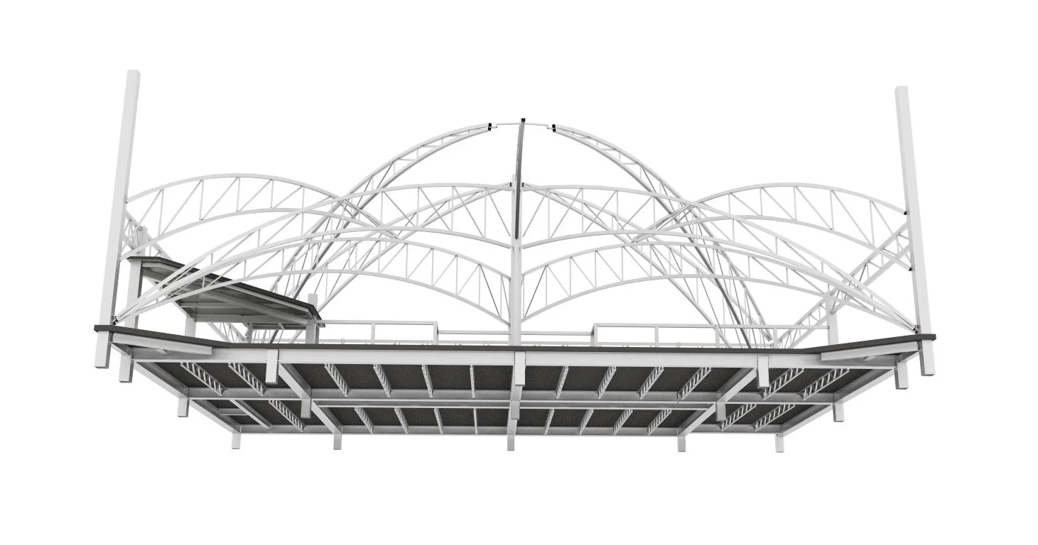
Accordingly, aluminum was chosen for the trusses and space frame because it was lightweight, non-corrosive, and able to bend into complex and precise shapes. Concrete was the material choice for the floors and partitions because of its diaphragm functionality, strength, and durability. Finally, the primary structure (including columns, beams, girders, deck and piles) was made up of steel components due to its strength, durability, sturdiness, and compactibility.
ASSEMBLY
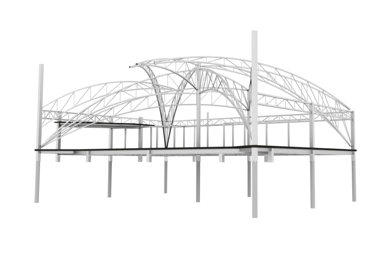
The primary structural components were shown in the exploded axonometric diagram, ordered from roof to foundation:
Stage Roof:
- Aluminum Trusses (also supporting the secondary Aluminum Space-Frame structure)
Mezzanine:
- Concrete on Steel Decking
- Tube Shaped HSS Beams
- Tube Shaped HSS Beam Girders
- Round Pipe Shaped HSS Columns
- W-Beam
Stage and Backstage:
- Tube Shaped HSS Beam Girders
- Concrete on Steel Decking
- W-Beams
- W-Beam Girders
- Open Web Steel Joists (OWSJ)
- Tube Shaped HSS Columns
- Round Pipe Shaped HSS Column
- Steel Pipe Piles
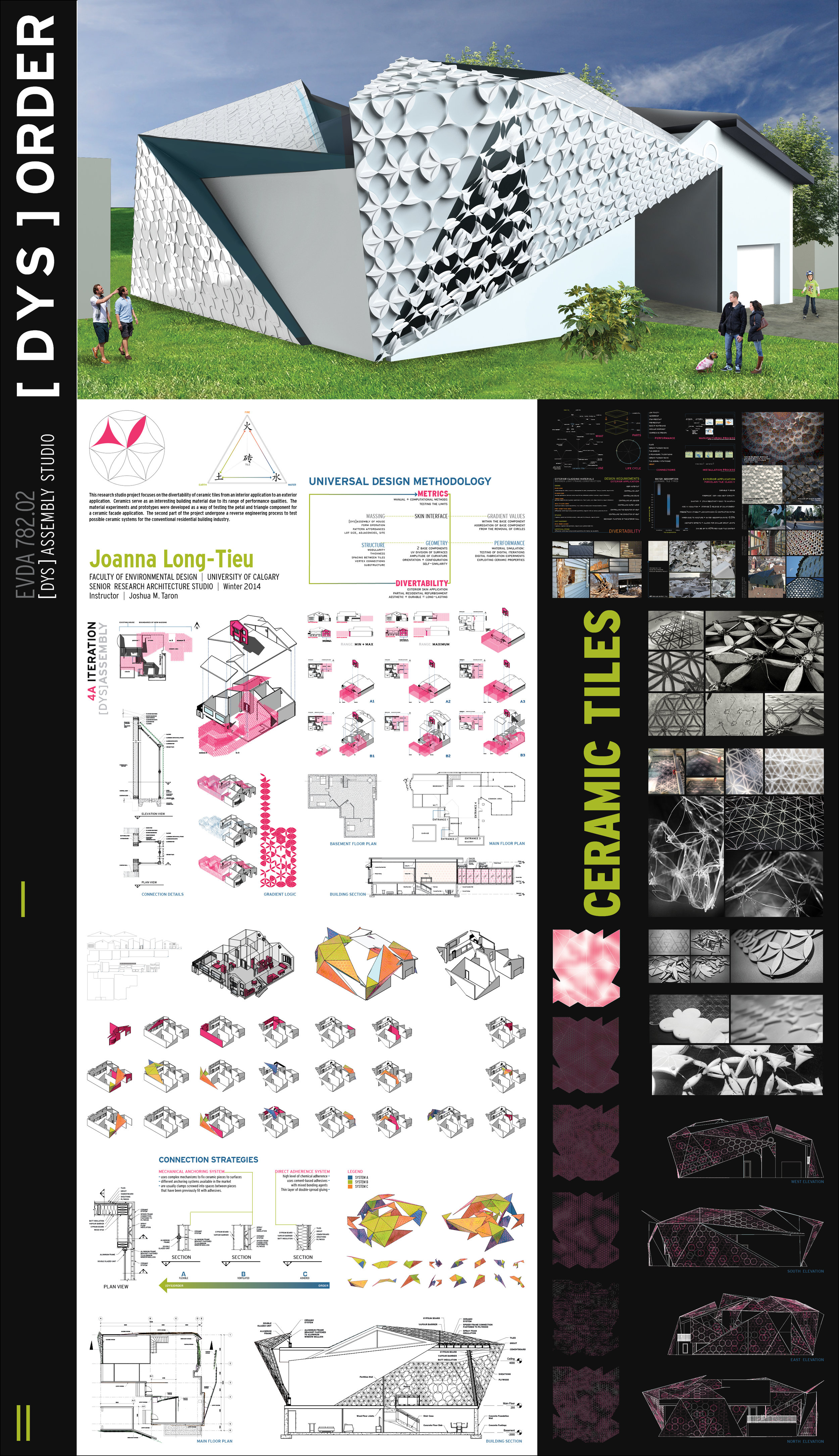
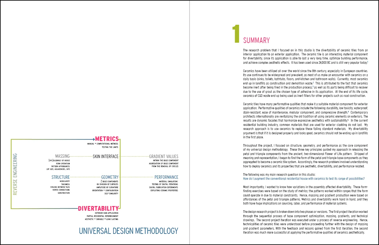
The research problem that I focused on in this studio is the divertability of ceramic tiles from an interior application to an exterior application. The ceramic tile is an interesting material component for divertability, since its application is able to last a very long time, optimize building performance, and achieve complex aesthetic effects. It has been used since 24,000 BC and is still very popular today.
Ceramics have been utilized all over the world since the 8th century, especially in European countries. Its use continues to be widespread and prevalent, as most of us make an encounter with ceramics on a daily basis (sinks, toilets, bathtubs, floors, and kitchen and bathroom walls). Currently, most ceramics end up in landfills as construction and demolition waste. This is attributed to the fact that ceramics become inert after being fired in the production process, as well as its parts being difficult to recover due to the use of grout as the chosen type of adhesive in its application. At the end of its life cycle, ceramics of C&D waste end up being used as inert fillers for other projects such as road construction.
Ceramic tiles have many performative qualities that make it a suitable material component for exterior application. Performative qualities of ceramics include the following: durability, low toxicity, waterproof, stain-resistant, ease of maintenance, modular component, and compressive strength. Contemporary architects internationally are revitalizing the old tradition of using ceramic elements on exteriors. The results are dynamic facades that harmonize expressive aesthetics with sustainability. In the current residential building industry, common materials that are used for exterior cladding do not last. My research approach is to use ceramics to replace these failing standard materials. My divertability argument is that if it is designed properly and looks good, ceramics should not be ending up in landfills in the first place.
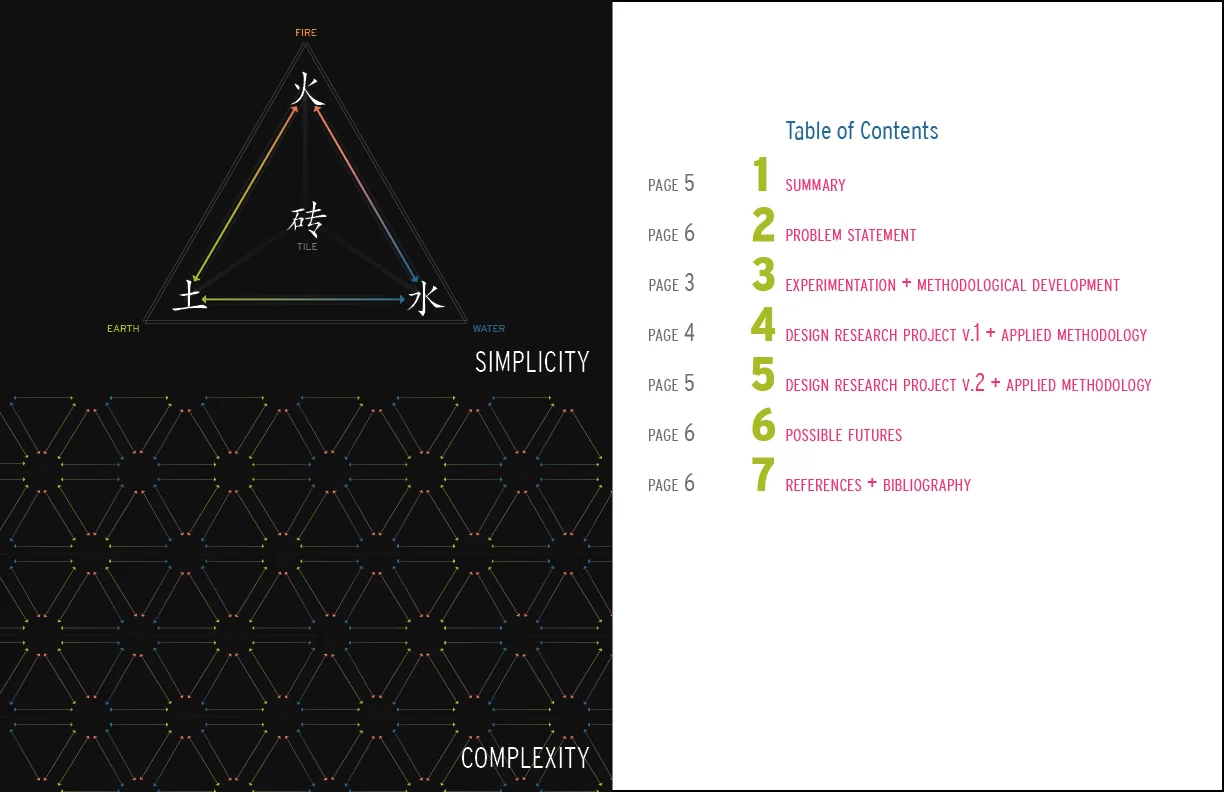
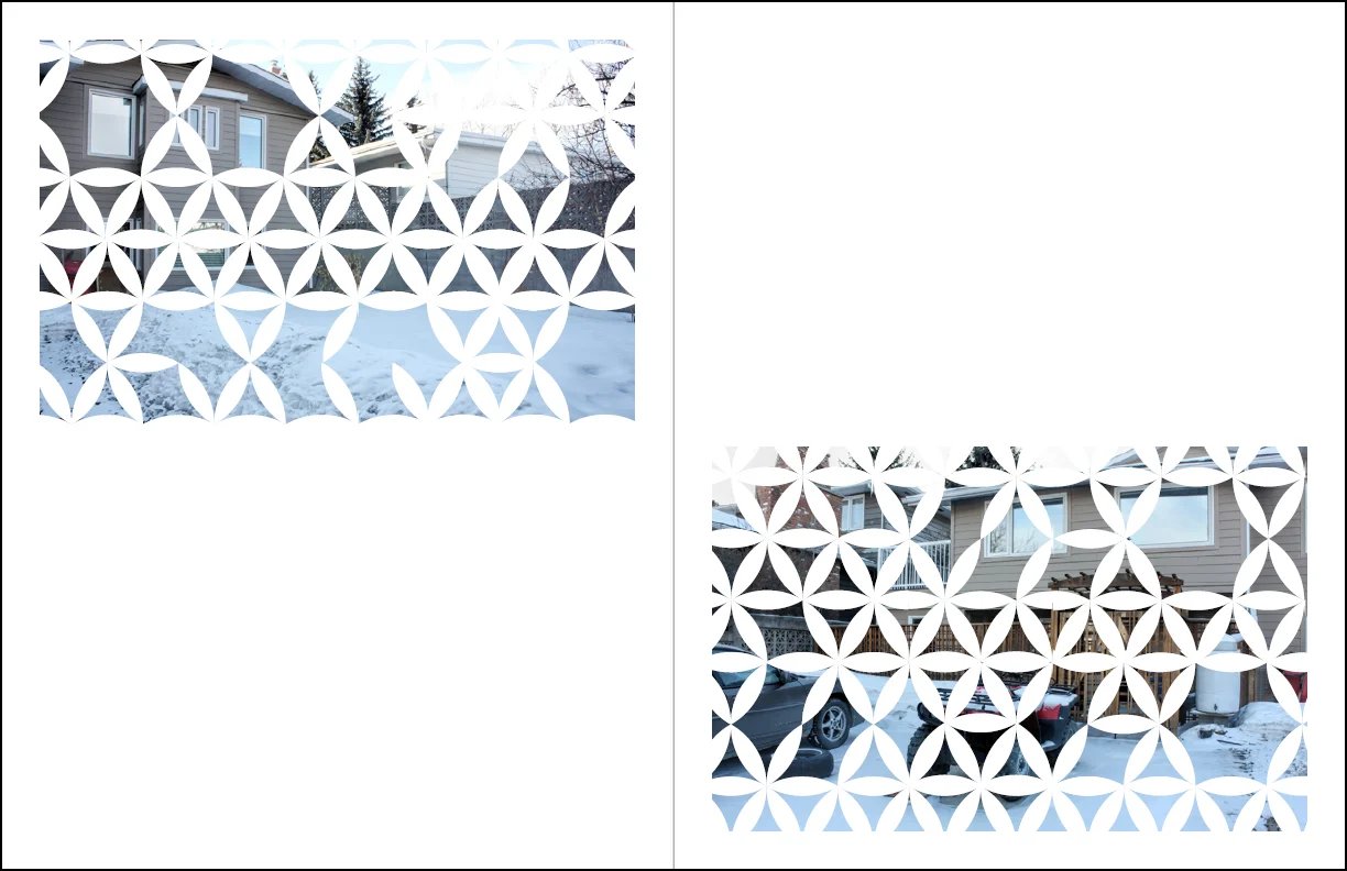
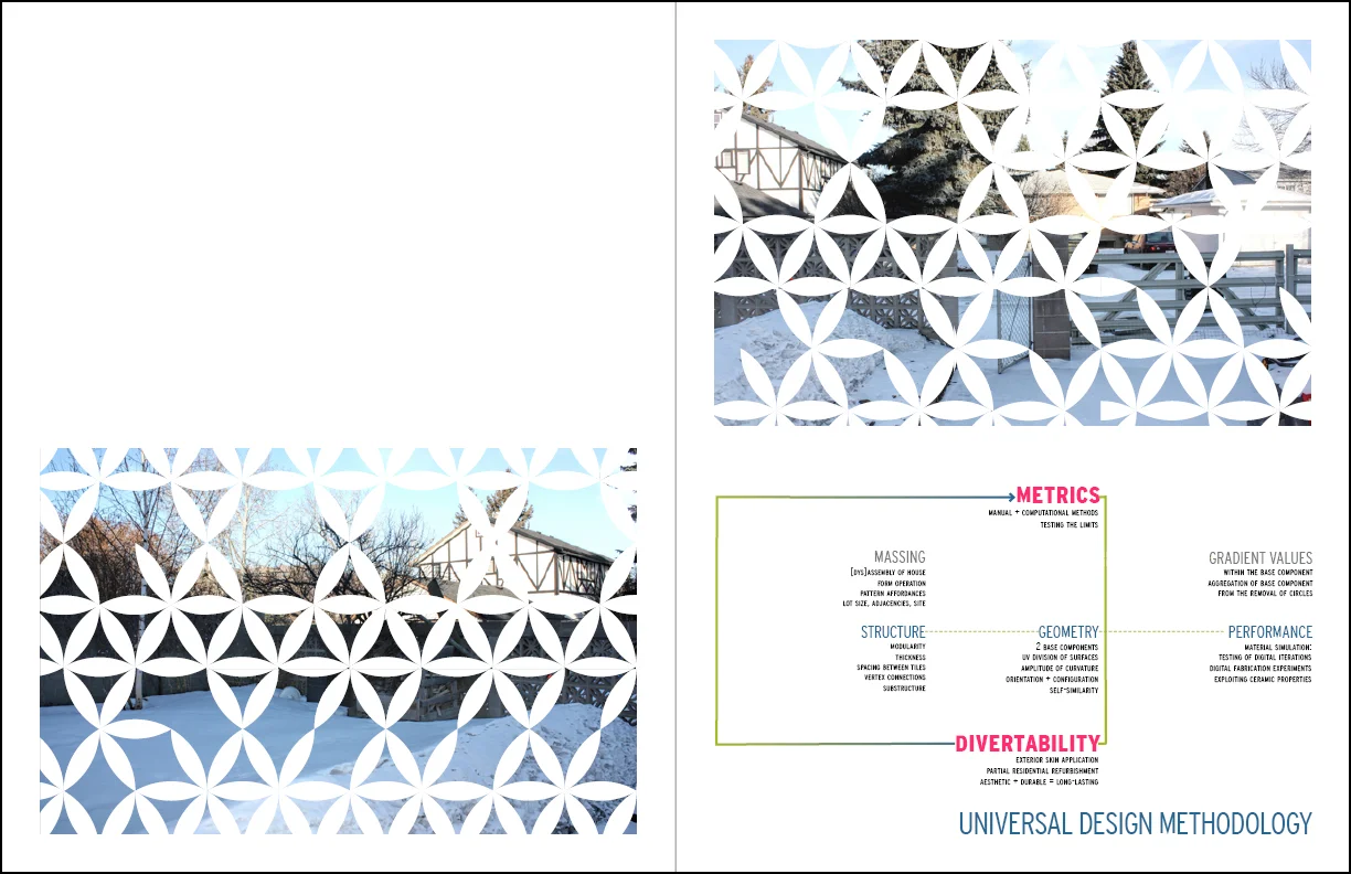
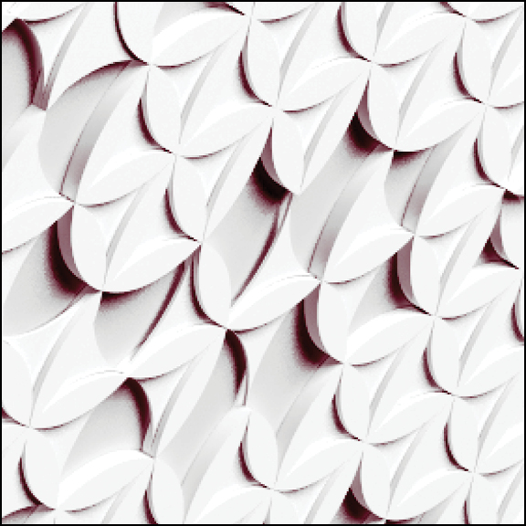
Throughout the project, I focused on structure, geometry, and performance as the core component of my universal design methodology. These three key principles guided my approach in releasing the petal and triangle components from the ancient, two-dimensional Flower of Life pattern. Stripped of meaning and representation, I began to find the form of the petal and triangle base components as they aggregated to become a ceramic tile system. Accordingly, the research problem involved understanding how to deploy ceramics and its properties that are aesthetic, divertability, and performance-related.
The following was my main research question in this studio:
How do I augment the conventional residential house with ceramics to test its range of possibilities?
Most importantly, I wanted to know how variations in the assembly affected divertability. These form-finding exercises were based on the study of metrics; the patterns worked within ranges that the form could operate in due to material constraints. Hence, massing and gradient production were based on affordances of the petal and triangle patterns. Metrics and divertability work hand in hand, and they both have huge implications on sourcing, labor, and performance of material systems.
The design research project is broken down into two phases or versions. The first project iteration worked through the sequential process of base component optimization, massing, gradients, and technical drawings. The second project iteration was executed under a process of reverse engineering. Hence, technicalities of ceramic tiles were understood before proceeding further with the design of massing and gradient parameters. With the feedback and lessons gained from the first iteration, the second iteration was much more successful at applying the performative qualities of ceramics aesthetically.
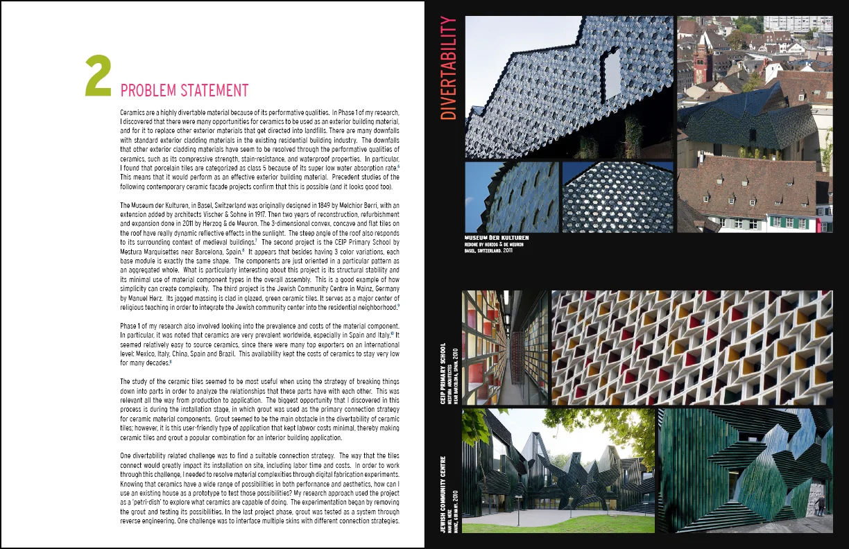
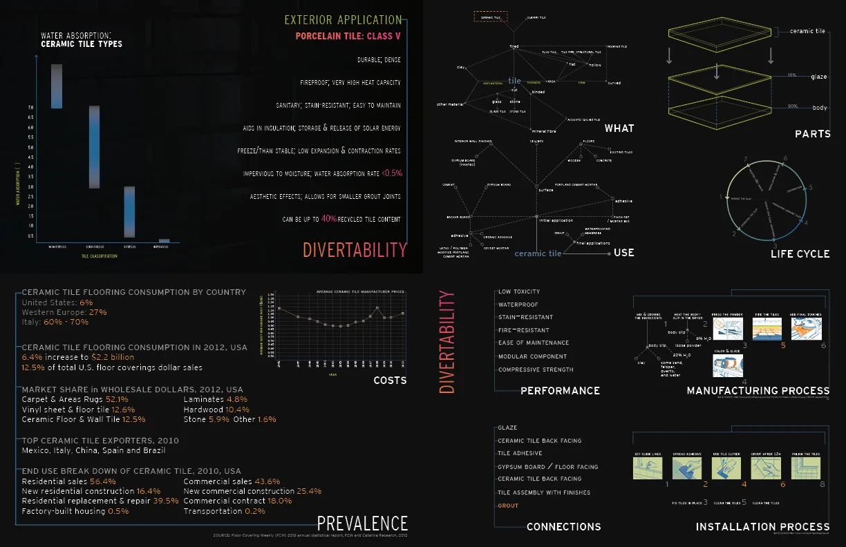
Ceramics are a highly divertable material because of its performative qualities. In Phase 1 of my research, I discovered that there were many opportunities for ceramics to be used as an exterior building material, and for it to replace other exterior materials that get directed into landfills. There are many downfalls with standard exterior cladding materials in the existing residential building industry. The downfalls that other exterior cladding materials have seem to be resolved through the performative qualities of ceramics, such as its compressive strength, stain-resistance, and waterproof properties. In particular, I found that porcelain tiles are categorized as class 5 because of its super low water absorption rate. This means that it would perform as an effective exterior building material. Precedent studies of the following contemporary ceramic facade projects confirm that this is possible (and it looks good too).
The Museum der Kulturen, in Basel, Switzerland was originally designed in 1849 by Melchior Berri, with an extension added by architects Vischer & Sohne in 1917. Then two years of reconstruction, refurbishment and expansion done in 2011 by Herzog & de Meuron. The 3-dimensional convex, concave and flat tiles on the roof have really dynamic reflective effects in the sunlight. The steep angle of the roof also responds to its surrounding context of medieval buildings.7The second project is the CEIP Primary School by Mestura Marquisettes near Barcelona, Spain. It appears that besides having 3 color variations, each base module is exactly the same shape. The components are just oriented in a particular pattern as an aggregated whole. What is particularly interesting about this project is its structural stability and its minimal use of material component types in the overall assembly. This is a good example of how simplicity can create complexity. The third project is the Jewish Community Centre in Mainz, Germany by Manuel Herz. Its jagged massing is clad in glazed, green ceramic tiles. It serves as a major center of religious teaching in order to integrate the Jewish community center into the residential neighborhood.
Phase 1 of my research also involved looking into the prevalence and costs of the material component. In particular, it was noted that ceramics are very prevalent worldwide, especially in Spain and Italy. It seemed relatively easy to source ceramics, since there were many top exporters on an international level: Mexico, Italy, China, Spain and Brazil. This availability kept the costs of ceramics to stay very low for many decades.
The study of the ceramic tiles seemed to be most useful when using the strategy of breaking things down into parts in order to analyze the relationships that these parts have with each other. This was relevant all the way from production to application. The biggest opportunity that I discovered in this process is during the installation stage, in which grout was used as the primary connection strategy for ceramic material components. Grout seemed to be the main obstacle in the divertability of ceramic tiles; however, it is this user-friendly type of application that kept labor costs minimal, thereby making ceramic tiles and grout a popular combination for an interior building application.
One divertability related challenge was to find a suitable connection strategy. The way that the tiles connect would greatly impact its installation on site, including labor time and costs. In order to work through this challenge, I needed to resolve material complexities through digital fabrication experiments. Knowing that ceramics have a wide range of possibilities in both performance and aesthetics, how can I use an existing house as a prototype to test those possibilities? My research approach used the project as a ‘petri-dish’ to explore what ceramics are capable of doing. The experimentation began by removing the grout and testing its possibilities. In the last project phase, grout was tested as a system through reverse engineering. One challenge was to interface multiple skins with different connection strategies.
The challenges and opportunities presented by ceramic tiles prompted the following questions that I would attempt to answer throughout my research in this studio:
How do variations in the assembly…
• affect the pattern that it uses?
• affect performance?
• affect divertability?
• aggregate as one system?
• change in metrics?
• impact the installation process?
• respond to the passage of water?
• aid in the overall insulation value?
• impact sunlight penetration?
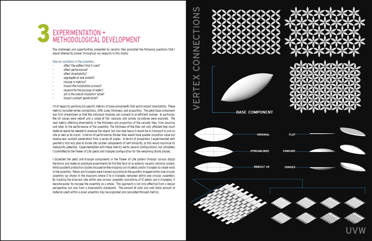
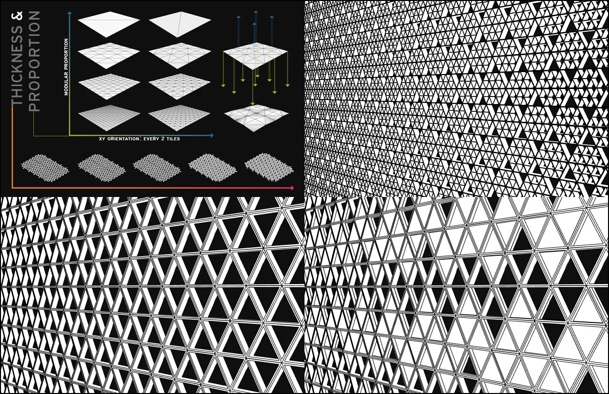
I first began by pointing out specific metrics of base components that would impact divertability. These metrics included vertex connections, UVW, scale, thickness, and proportion. The petal base component was first streamlined so that the individual modules can connect in an efficient manner. In particular, the UV values were rebuilt and a range of flat, concave, and convex curvatures were explored. The next metric affecting divertability is the thickness and proportion of the ceramic tiles, from sourcing and labor to the performance of the assembly. The thickness of the tiles not only affected how much material would be needed to produce the object, but also how heavy it would be to transport to and on site as well as to install. In terms of performance, thicker tiles would have greater insulation value but receive less sunlight penetration from a series of angles. In terms of proportion, I experimented with geometry that was able to divide into smaller components of self-similarity, as this would maximize its modularity potential. Experimentation with these metrics led to several configurations, but ultimately I committed to the Flower of Life (petal and triangle) configuration for the remaining studio phases.
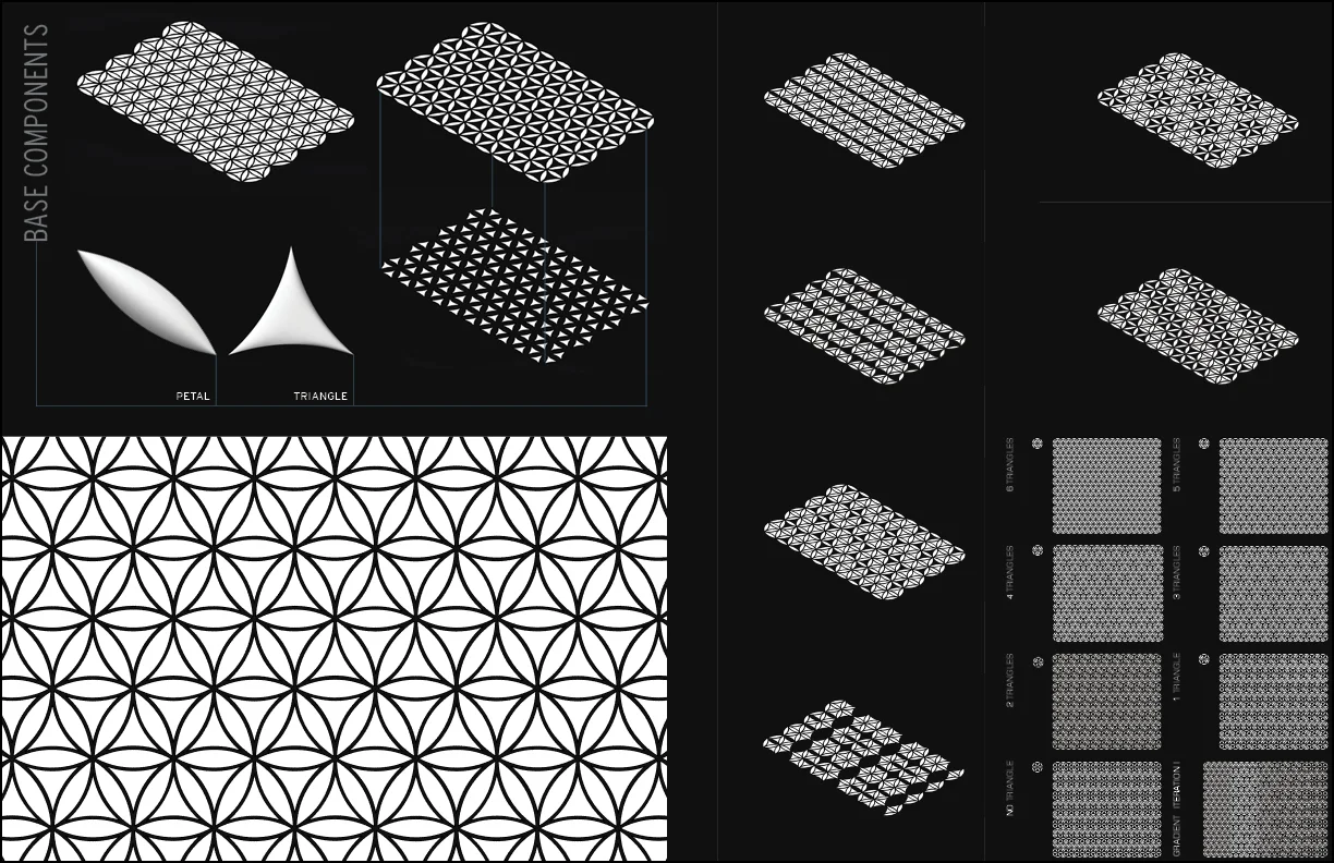
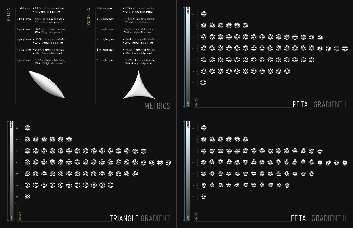
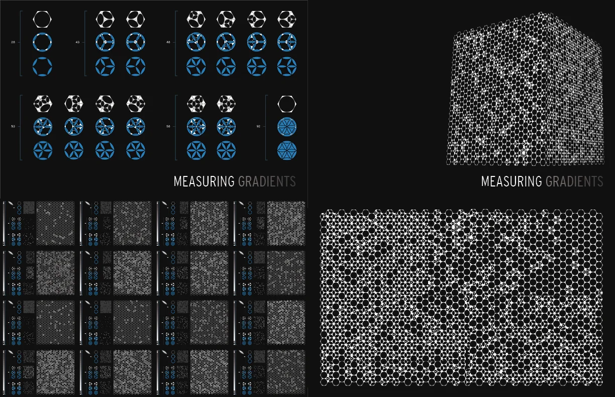
I dissected the petal and triangle components in the Flower of Life pattern through various digital iterations and material prototype experiments to find the form of an exterior ceramic skinning system. Initial gradient production studies focused on the dropping-out of petals and/or triangles to create voids in the assembly. Petals and triangles were tracked according to the quantity dropped within one circular assembly (as shown in the diagrams where 0 to 6 triangles remained within one circular assembly). By tracking the drop-out rate within one circular assembly (consisting of 12 petals and 6 triangles), it became easier to manage the assembly as a whole. This approach is not only effective from a design perspective, but also from a divertability standpoint. The amount of solid and void (total amount of material used) within a given assembly may be organized and calculated through metrics.
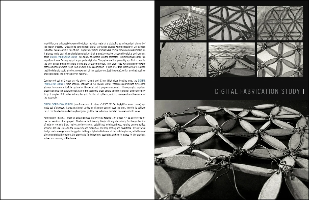
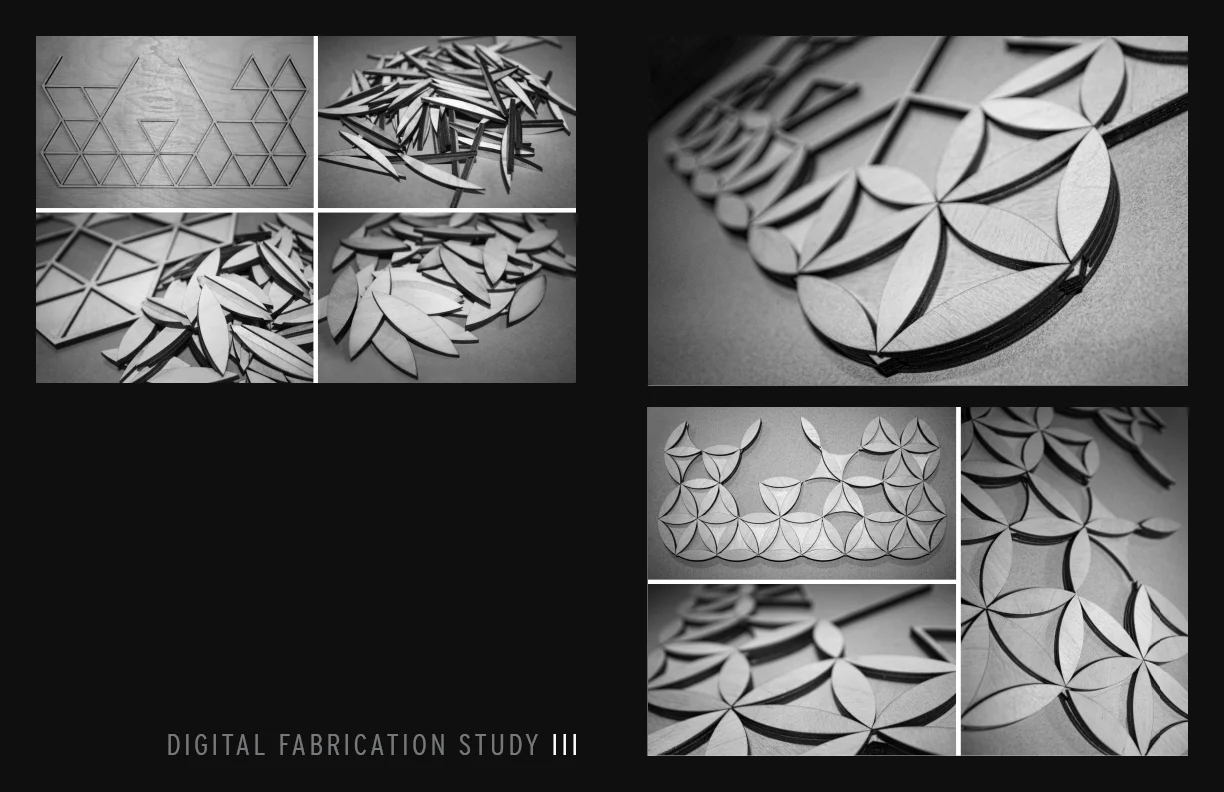
In addition, my universal design methodology included material prototyping as an important element of the design process. I was able to conduct four digital fabrication studies with the Flower of Life pattern to further my research in this studio. Digital fabrication studies were crucial for design development, as it allowed me to deal with material complexities that are not accessible through the digital environment itself. digital fabrication study I was done 2 to 3 weeks into the semester. The materials used for this experiment were 3mm gray taskboard and metal wire. The pattern of the assembly was first scored by the laser cutter, then holes were drilled and threaded through. The ‘grout’ gap was then removed—the petal components were freed from its two-dimensional form. It was after this exercise that I realized that the triangle could also be a component of this system (not just the petal), which also had positive implications for the divertability of material.
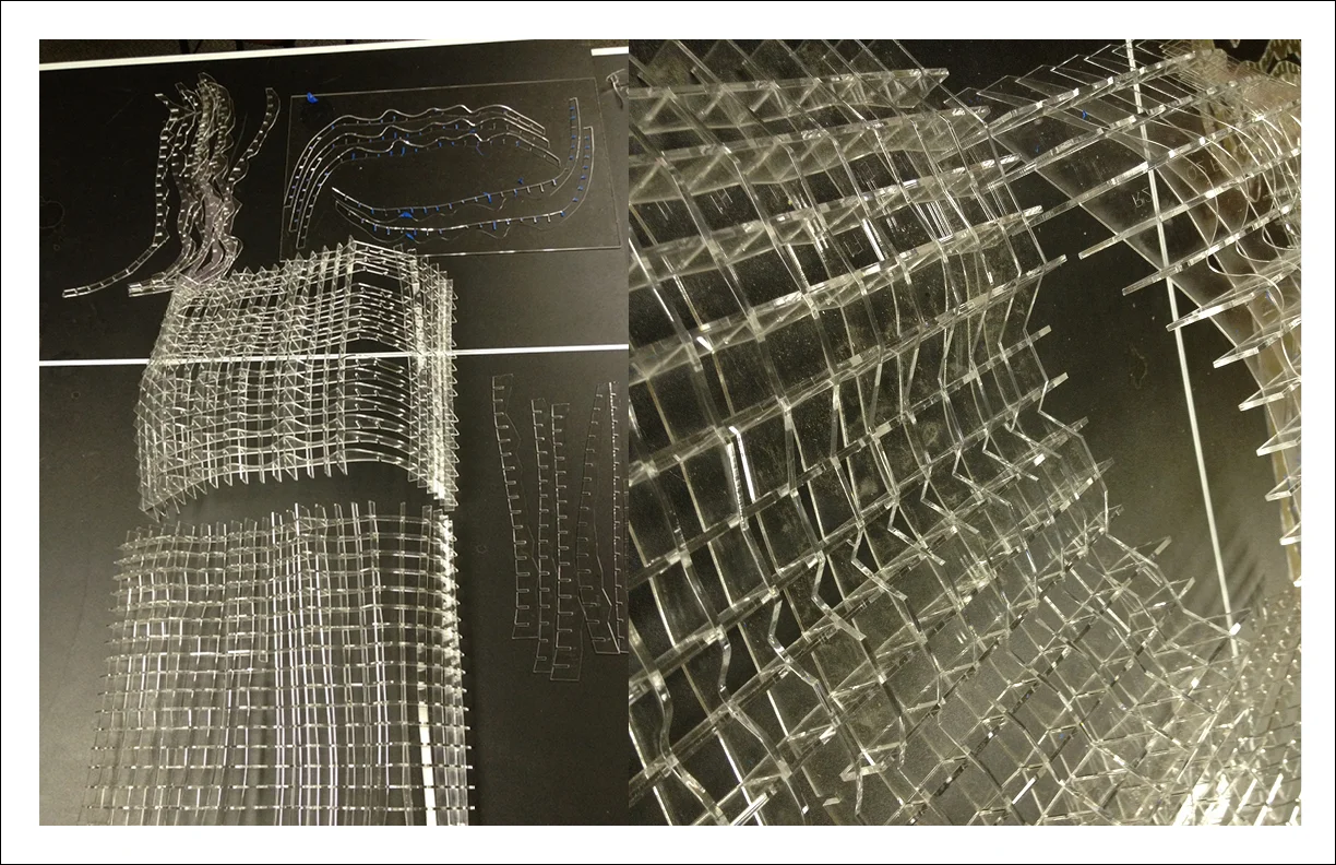
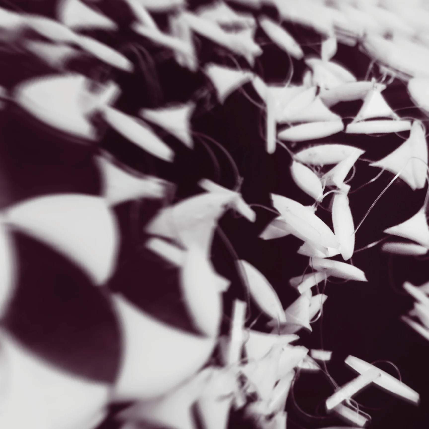
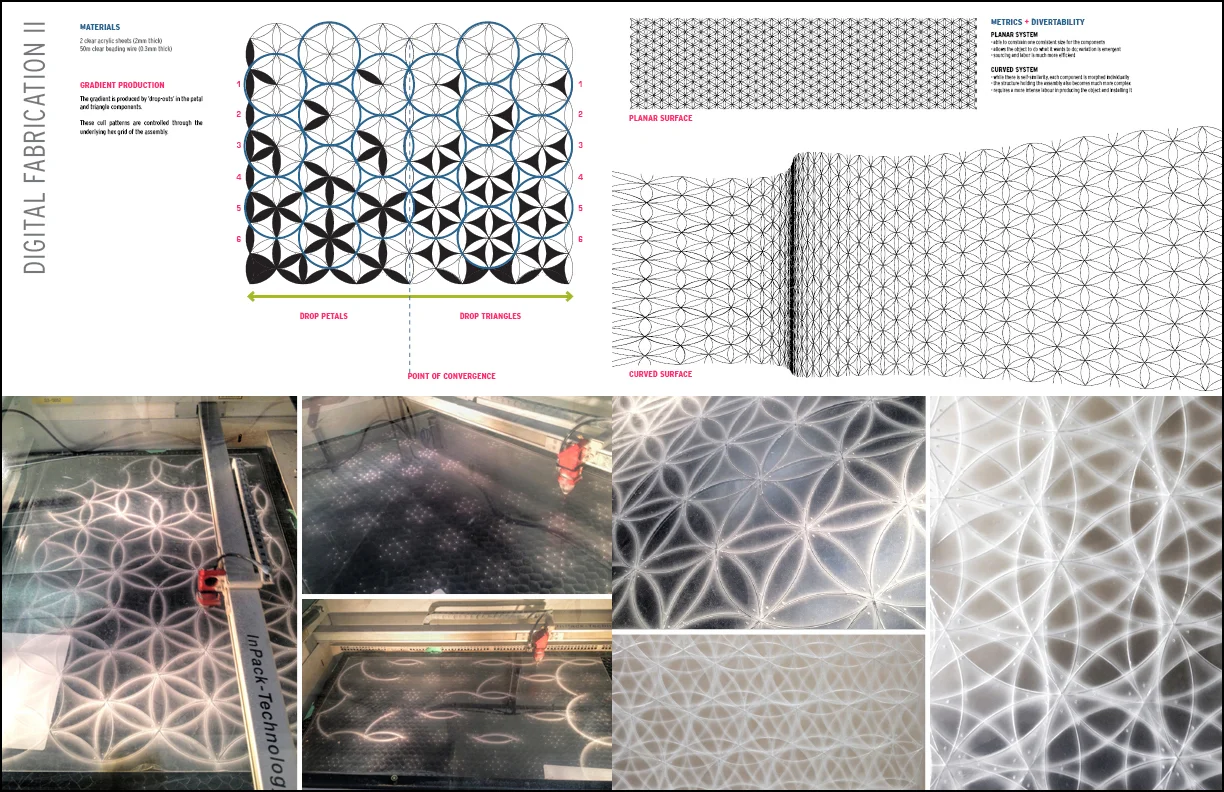
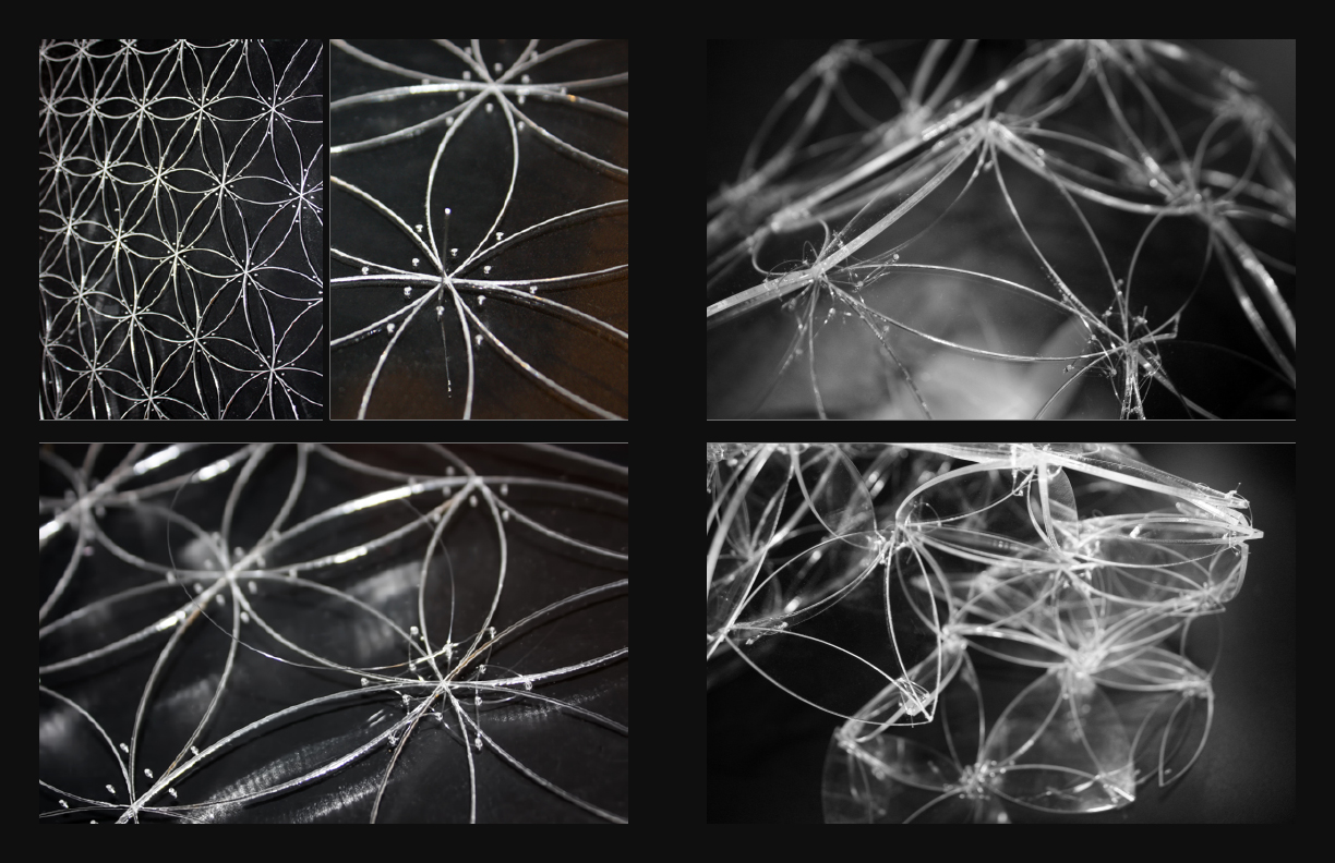
Constructed out of 2 clear acrylic sheets (2mm) and 0.3mm thick clear beading wire, digital fabrication study II was my second attempt to create a flexible system for the petal and triangle components. I incorporated gradient production into this study: the left half of the assembly drops petals, and the right half of the assembly drops triangles. Both sides follow a hex-grid for its cull patterns, which converges down the center of the assembly. Digital fabrication study III was made out of plywood. It was an attempt to design with more control over the form. In order to achieve this, I constructed an underlying triangular grid for the individual modules to cover on both sides.
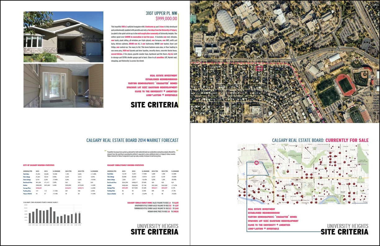
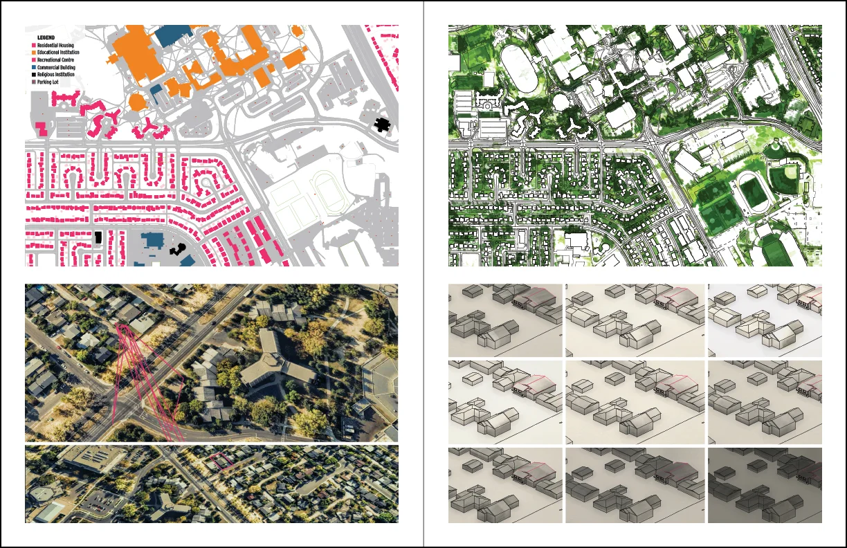
At the end of Phase 3, I chose an existing house in University Heights (3107 Upper Pl) as a prototype for the two versions of my project. The house in University Heights fit my site criteria for the application of exterior ceramic tiles: real estate investment, established neighbourhood, varying demographics, spacious lot size, close to the university and amenities, and long-lasting and divertable. My universal design methodology would be applied in the partial refurbishment of this existing house, with the goal of using metrics throughout the process to find structure, geometry, and performance for the gradient values and massing of the house.
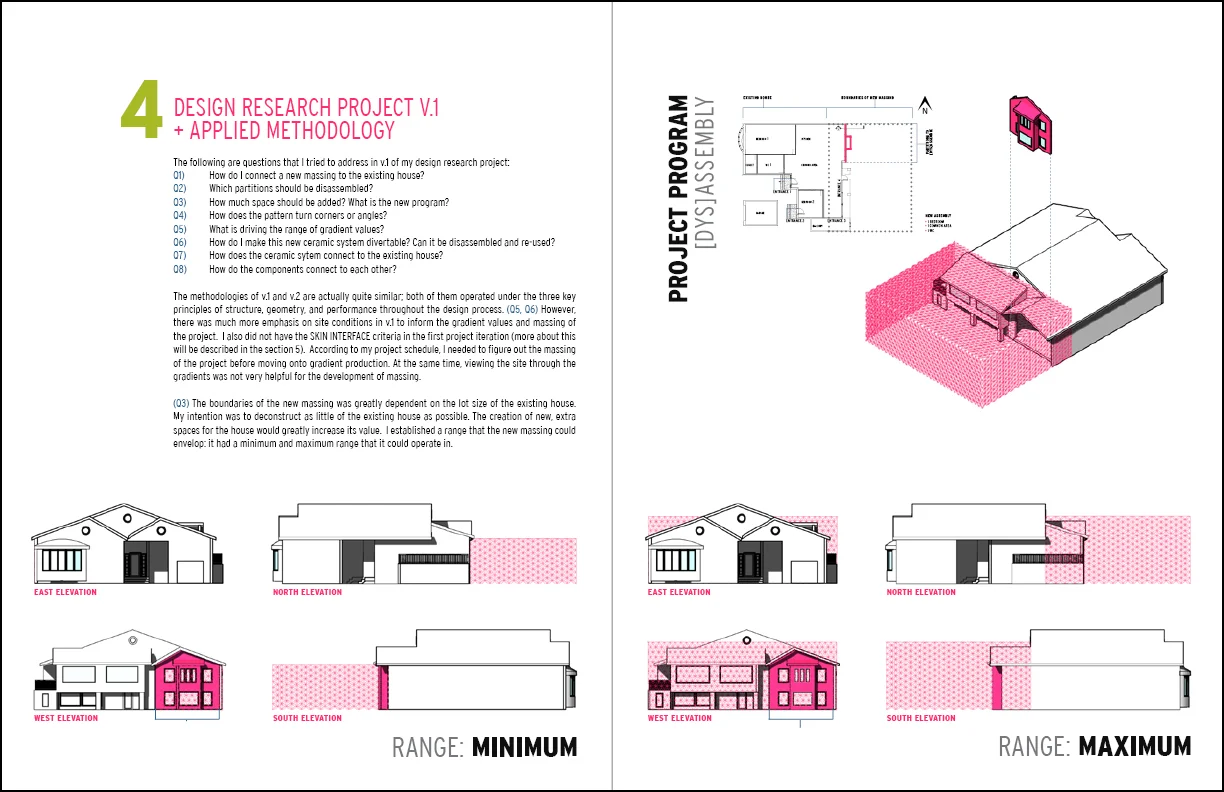
The following are questions that I tried to address in v.1 of my design research project:
Q1) How do I connect a new massing to the existing house?
Q2) Which partitions should be disassembled?
Q3) How much space should be added? What is the new program?
Q4) How does the pattern turn corners or angles?
Q5) What is driving the range of gradient values?
Q6) How do I make this new ceramic system divertable? Can it be disassembled and re-used?
Q7) How does the ceramic sytem connect to the existing house?
Q8) How do the components connect to each other?
The methodologies of v.1 and v.2 are actually quite similar; both of them operated under the three key principles of structure, geometry, and performance throughout the design process. (Q5, Q6) However, there was much more emphasis on site conditions in v.1 to inform the gradient values and massing of the project. I also did not have the SKIN INTERFACE criteria in the first project iteration (more about this will be described in the section 5). According to my project schedule, I needed to figure out the massing of the project before moving onto gradient production. At the same time, viewing the site through the gradients was not very helpful for the development of massing.
(Q3) The boundaries of the new massing was greatly dependent on the lot size of the existing house. My intention was to deconstruct as little of the existing house as possible. The creation of new, extra spaces for the house would greatly increase its value. I established a range that the new massing could envelop: it had a minimum and maximum range that it could operate in.
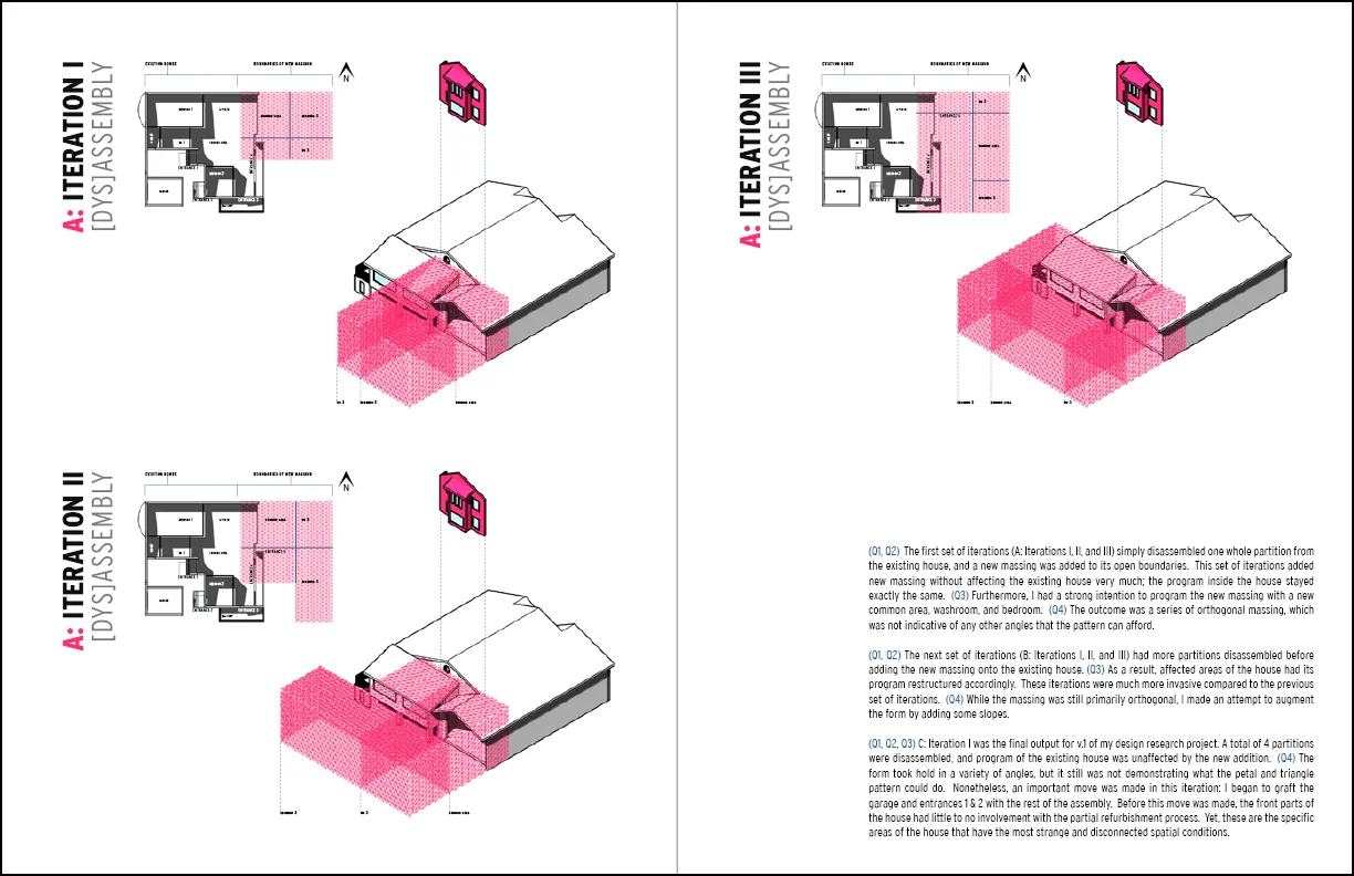
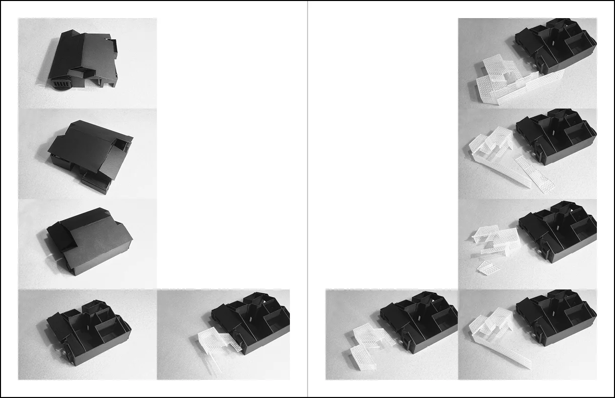
(Q1, Q2) The first set of iterations (A: Iterations I, II, and III) simply disassembled one whole partition from the existing house, and a new massing was added to its open boundaries. This set of iterations added new massing without affecting the existing house very much; the program inside the house stayed exactly the same. (Q3) Furthermore, I had a strong intention to program the new massing with a new common area, washroom, and bedroom. (Q4) The outcome was a series of orthogonal massing, which was not indicative of any other angles that the pattern can afford.
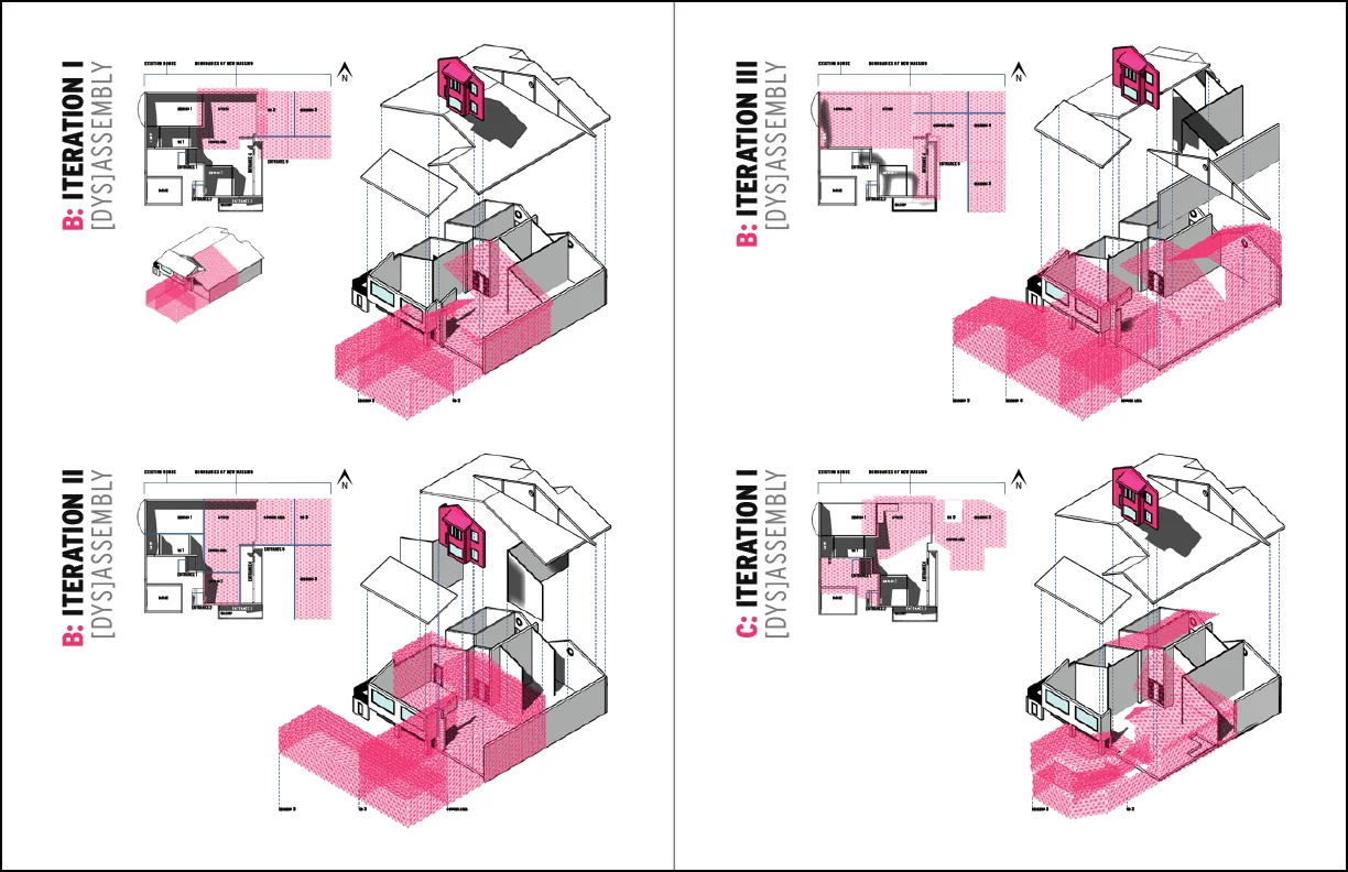
(Q1, Q2) The next set of iterations (B: Iterations I, II, and III) had more partitions disassembled before adding the new massing onto the existing house. (Q3) As a result, affected areas of the house had its program restructured accordingly. These iterations were much more invasive compared to the previous set of iterations. (Q4) While the massing was still primarily orthogonal, I made an attempt to augment the form by adding some slopes.
(Q1, Q2, Q3) Iteration I was the final output for v.1 of my design research project. A total of 4 partitions were disassembled, and program of the existing house was unaffected by the new addition.
(Q4) The form took hold in a variety of angles, but it still was not demonstrating what the petal and triangle pattern could do. Nonetheless, an important move was made in this iteration: I began to graft the garage and entrances 1 & 2 with the rest of the assembly. Before this move was made, the front parts of the house had little to no involvement with the partial refurbishment process. Yet, these are the specific areas of the house that have the most strange and disconnected spatial conditions.
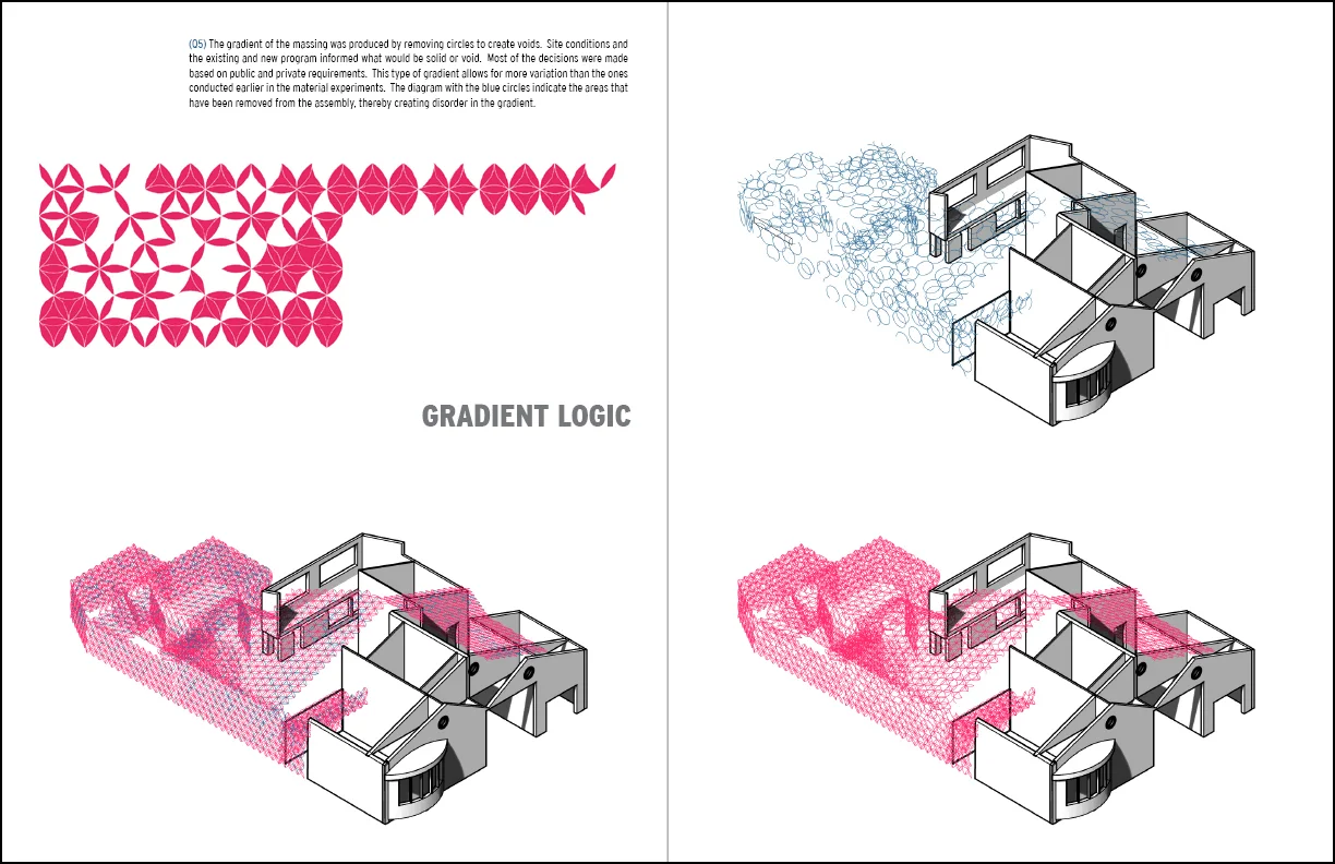
(Q5) The gradient of the massing was produced by removing circles to create voids. Site conditions and the existing and new program informed what would be solid or void. Most of the decisions were made based on public and private requirements. This type of gradient allows for more variation than the ones conducted earlier in the material experiments. The diagram with the blue circles indicate the areas that have been removed from the assembly, thereby creating disorder in the gradient.
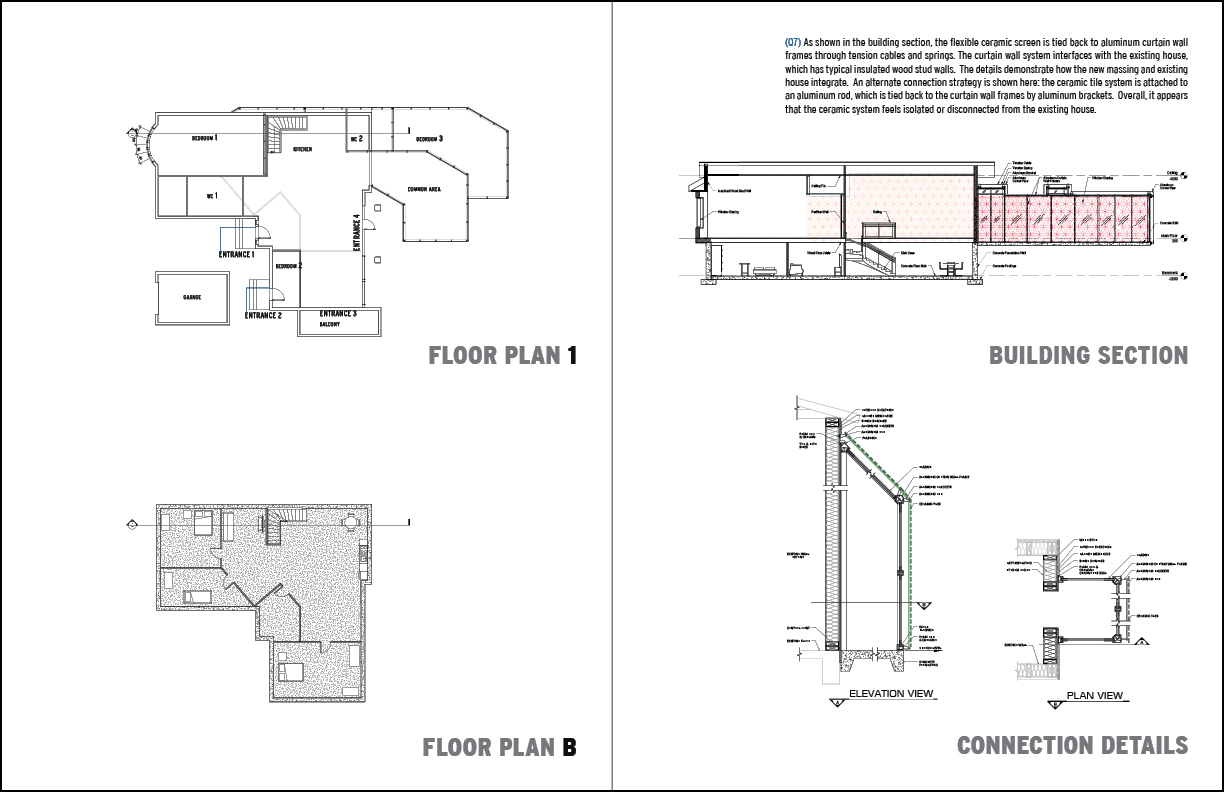
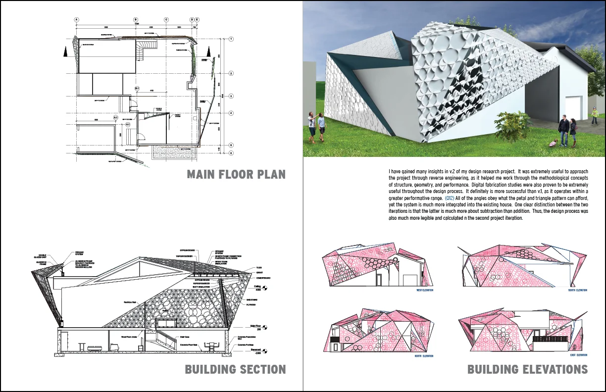
(Q7) As shown in the building section, the flexible ceramic screen is tied back to aluminum curtain wall frames through tension cables and springs. The curtain wall system interfaces with the existing house, which has typical insulated wood stud walls. The details demonstrate how the new massing and existing house integrate. An alternate connection strategy is shown here: the ceramic tile system is attached to an aluminum rod, which is tied back to the curtain wall frames by aluminum brackets. Overall, it appears that the ceramic system feels isolated or disconnected from the existing house.
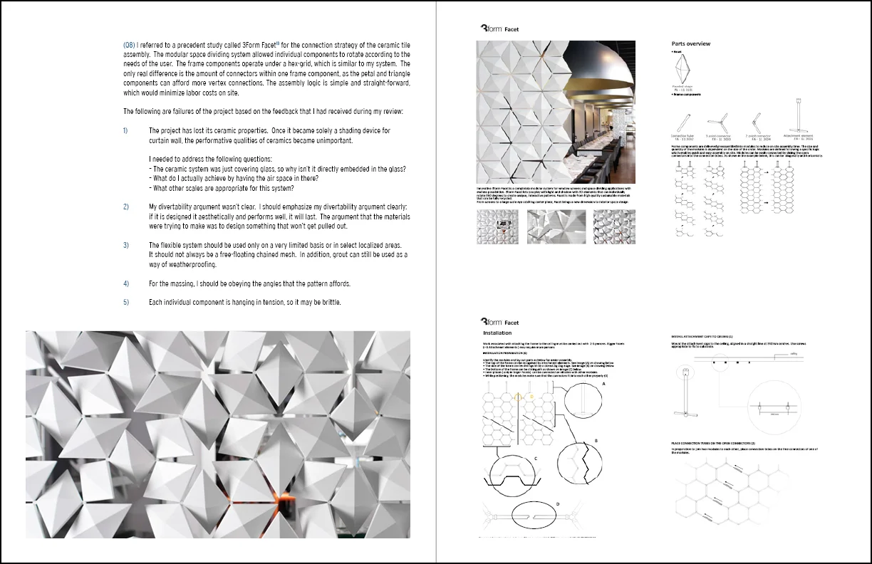
(Q8) I referred to a precedent study called 3Form Facet for the connection strategy of the ceramic tile assembly. The modular space dividing system allowed individual components to rotate according to the needs of the user. The frame components operate under a hex-grid, which is similar to my system. The only real difference is the amount of connectors within one frame component, as the petal and triangle components can afford more vertex connections. The assembly logic is simple and straight-forward, which would minimize labor costs on site.
The following are failures of the project based on the feedback that I had received during my review:
1) The project has lost its ceramic properties. Once it became solely a shading device for a curtain wall, the performative qualities of ceramics became unimportant. I needed to address the following questions:
– The ceramic system was just covering glass, so why isn’t it directly embedded in the glass?
– What do I actually achieve by having the air space in there?
– What other scales are appropriate for this system?
2) My divertability argument wasn’t clear. I should emphasize my divertability argument clearly: if it is designed it aesthetically and performs well, it will last. The argument that the materials were trying to make was to design something that won’t get pulled out.
3) The flexible system should be used only on a very limited basis or in select localized areas. It should not always be a free-floating chained mesh. In addition, grout can still be used as a way of weatherproofing.
4) For the massing, I should be obeying the angles that the pattern affords.
5) Each individual component is hanging in tension, so it may be brittle.
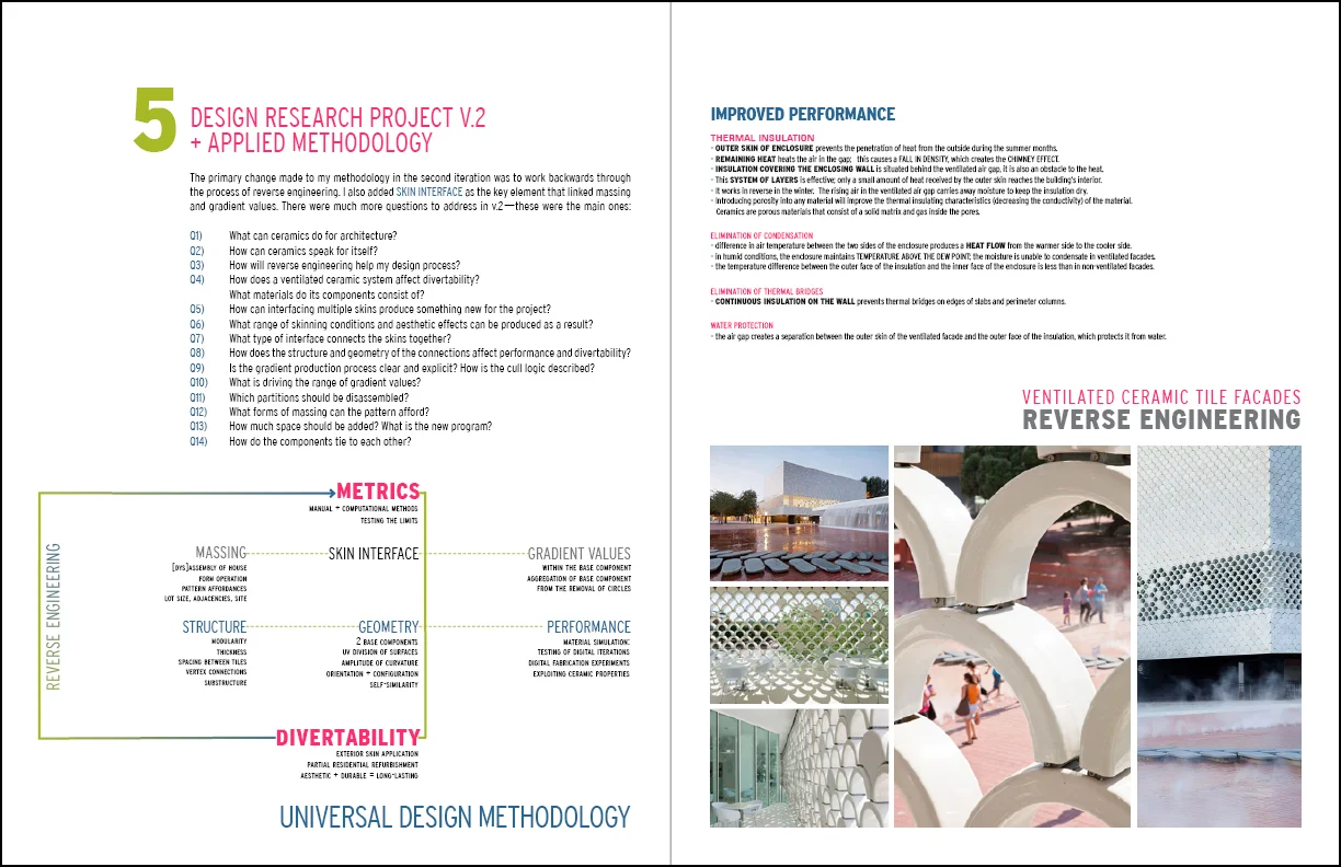
The primary change made to my methodology in the second iteration was to work backwards through the process of reverse engineering. I also added SKIN INTERFACE as the key element that linked massing and gradient values. There were much more questions to address in v.2—these were the main ones:
Q1) What can ceramics do for architecture?
Q2) How can ceramics speak for itself?
Q3) How will reverse engineering help my design process?
Q4) How does a ventilated ceramic system affect divertability? What materials do its components consist of?
Q5) How can interfacing multiple skins produce something new for the project?
Q6) What range of skinning conditions and aesthetic effects can be produced as a result?
Q7) What type of interface connects the skins together?
Q8) How does the structure and geometry of the connections affect performance and divertability?
Q9) Is the gradient production process clear and explicit? How is the cull logic described?
Q10) What is driving the range of gradient values?
Q11) Which partitions should be disassembled?
Q12) What forms of massing can the pattern afford?
Q13) How much space should be added? What is the new program?
Q14) How do the components tie to each other?
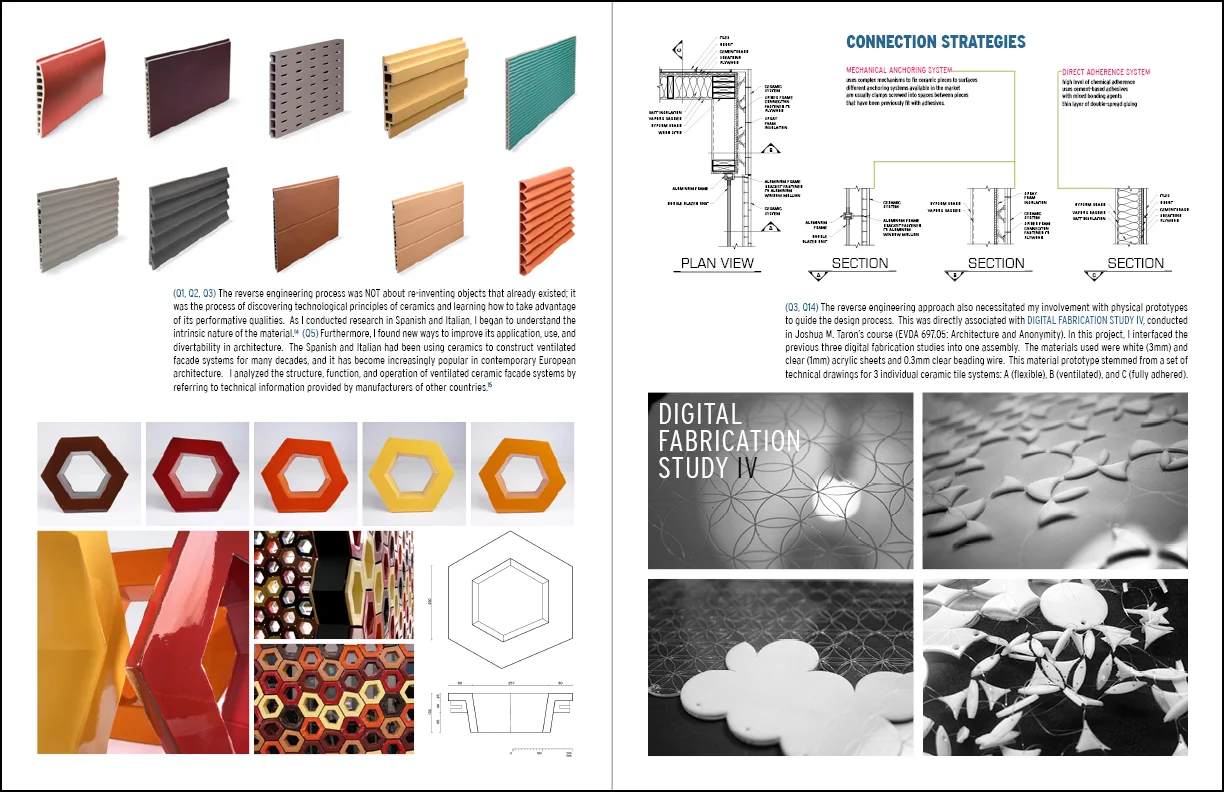
(Q1, Q2, Q3) The reverse engineering process was NOT about re-inventing objects that already existed; it was the process of discovering technological principles of ceramics and learning how to take advantage of its performative qualities. As I conducted research in Spanish and Italian, I began to understand the intrinsic nature of the material.14(Q5) Furthermore, I found new ways to improve its application, use, and divertability in architecture. The Spanish and Italian had been using ceramics to construct ventilated facade systems for many decades, and it has become increasingly popular in contemporary European architecture. I analyzed the structure, function, and operation of ventilated ceramic facade systems by referring to technical information provided by manufacturers of other countries.
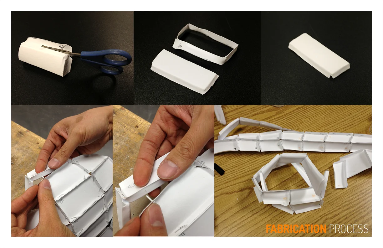
(Q3, Q14) The reverse engineering approach also necessitated my involvement with physical prototypes to guide the design process. This was directly associated with digital fabrication study IV. In this project, I interfaced the previous three digital fabrication studies into one assembly. The materials used were white (3mm) and clear (1mm) acrylic sheets and 0.3mm clear beading wire. This material prototype stemmed from a set of technical drawings for 3 individual ceramic tile systems: A (flexible), B (ventilated), and C (fully adhered).
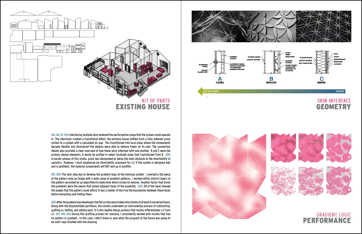
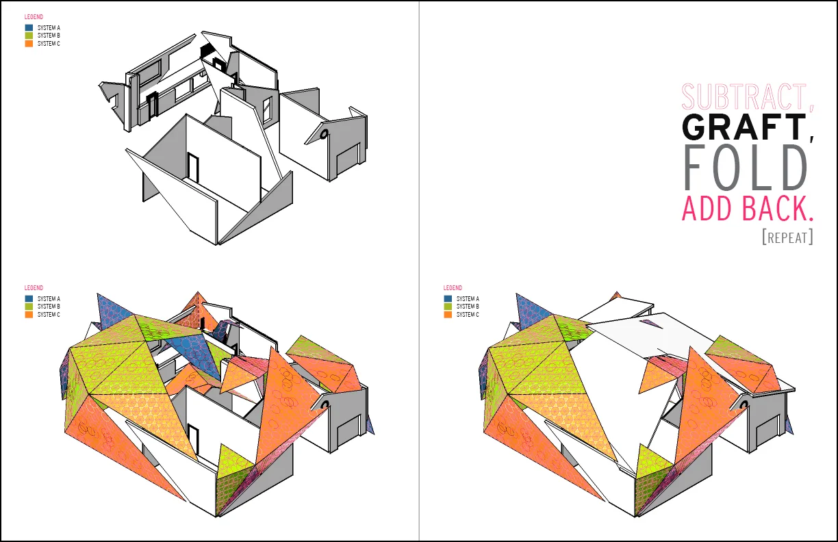
(Q5, Q6, Q7, Q14) Interfacing multiple skins widened the performative range that the system could operate in. The interfaces created a transitional effect: the existing house shifted from a fully adhered grout system to a system with a calculated air gap. This transitioned into local areas where the components became flexible and disordered—the objects were able to behave freely on its own. The connection details plan provides a clear overview of how these skins interface with one another. B and C were the primary design elements; A would be grafted in select localized areas that transitioned from B. (Q8) In earlier phases of this studio, grout was designated as being the main obstacle to the divertability of ceramics. However, I must emphasize my divertability argument for v.2: if the system is designed well and is aesthetic, the material components will NOT end up in landfills.
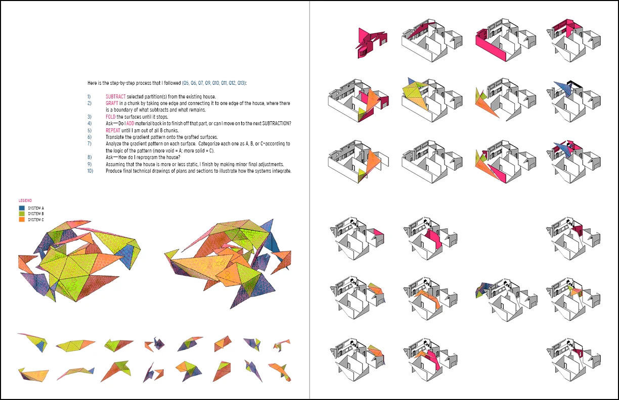
(Q9, Q10) The next step was to develop the gradient logic of the skinning system. I overlaid a flat piece of the pattern onto an image with a wide range of gradient patterns. I worked within distinct layers of the pattern (provided by an algorithm) to determine which circles to remove. Another factor that drove the gradients were the seams that joined adjacent faces of the assembly. (Q12) All of the faces obeyed the angles that the pattern could afford; it was a matter of blurring the boundaries between these faces before extracting and folding them.
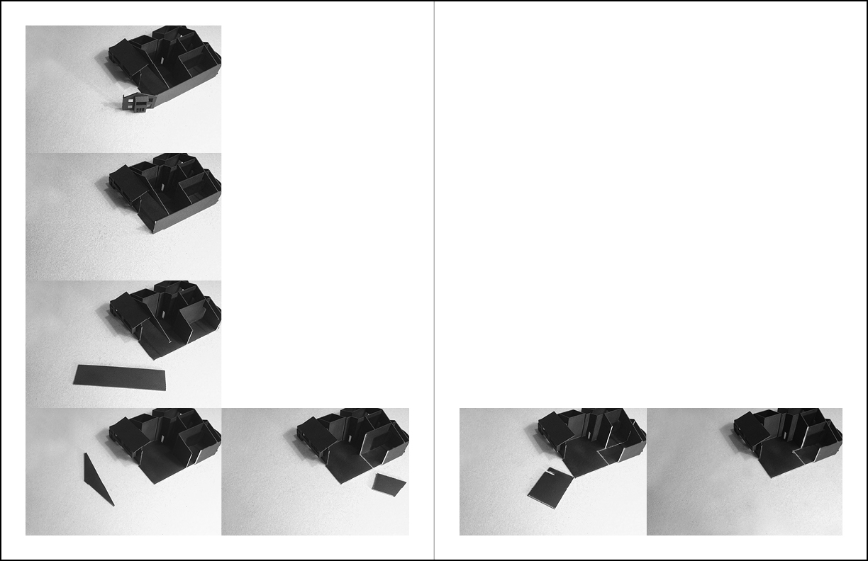
(Q11) After the gradient was developed, the flat surface was broken into chunks of at least 3 connected faces. Along with the disassembled partitions, the chunks underwent an instrumental process of subtracting, grafting in, folding, and adding back. It is this legible design process that mostly differentiates v.2 from v.1. (Q9, Q10, Q13) During this grafting process for massing, I consistently worked with chunks that had no pattern or gradient. In this case, I didn’t know or plan what the program of the house was going to be until I was finished with the massing.
Here is the step-by-step process that I followed (Q5, Q6, Q7, Q9, Q10, Q11, Q12, Q13):
1) SUBTRACT selected partition(s) from the existing house.
2) GRAFT in a chunk by taking one edge and connecting it to one edge of the house, where there is a boundary of what subtracts and what remains.
3) FOLD the surfaces until it stops.
4) Ask—Do I ADD material back in to finish off that part, or can I move on to the next SUBTRACTION?
5) Repeat until I am out of all 8 chunks.
6) Translate the gradient pattern onto the grafted surfaces.
7) Analyze the gradient pattern on each surface. Categorize each one as A, B, or C—according to the logic of the pattern (more void = A; more solid = C).
8) Ask—How do I reprogram the house?
9) Assuming that the house is more or less static, I finish by making minor final adjustments.
10) Produce final technical drawings of plans and sections to illustrate how the systems integrate.
I have gained many insights in v.2 of my design research project. It was extremely useful to approach the project through reverse engineering, as it helped me work through the methodological concepts of structure, geometry, and performance. Digital fabrication studies were also proven to be extremely useful throughout the design process. It definitely is more successful than v.1, as it operates within a greater performative range. (Q12) All of the angles obey what the petal and triangle pattern can afford, yet the system is much more integrated into the existing house. One clear distinction between the two iterations is that the latter is much more about subtraction than addition. Thus, the design process was also much more legible and calculated n the second project iteration.
Research territories that open up include the study of parametric or computational design, the search for innovative techniques to augment conventional materials, strategies to track, control, and decrease construction and demolition waste, and object-oriented architecture.
My research in this studio has opened up many questions to speculate on:
Q1) How can I balance the amount of control that I have over the object that I am designing with? When does it become too much, thereby straying away from an object-oriented point of view?
Q2) How can I begin to design parametrically, without having to manually generate iterations?
Q3) How many times should I repeat questions that I am asking throughout the design process? Do I always trust answers coming from my instincts?
Q4) How can reverse engineering inform my future projects?
Q5) How do I incorporate the process of subtraction into my future projects?
Q6) What is the future of objects?
Q7) How can I design as a pioneer of the future?
Q8) What are some more techniques in finding affordances of a particular object?
Q9) What can the North American building industry learn from international countries?
The term has changed my perspective on the design process, as I have learnt that it is very useful to produce a design, and then dedicate time towards analysis and speculation. A good design is process-driven, not prescribed. I also learnt that it is very important to stay focused on the task at hand, and to be very clear with the questions that I intend to ask during the design process. I will most likely receive answers if I am very explicit about what I answers I need.
In this studio and in my elective course, I have discovered that the act of mapping is an act of reproducing the object itself. By repeating patterns of an object, one becomes more and more familiar with the object’s natural tendencies. The digital fabrication experiments has proved that the former is true. The notion of autonomy in architecture was implemented into the work of this studio. Before this term, I did not envision architecture as being an object.
Perhaps the most important lesson that I learnt in this studio is that there is NO right or wrong way to approach a design. There doesn’t have to be a reason for everything, especially when it comes to representation or symbolism. These anthropocentric views are subjective and biased: it clearly is not designing for the future.
This studio has proved the importance of digital fabrication in the design process. Interaction with the objects in various forms has contributed a great deal to my understanding of it. Material studies can provide answers that the digital environment simply cannot handle. Physical models allowed me to deal with material complexities of the object, thereby deepening my objective perception of how it wants to operate. I will experiment with more form-finding techniques in the future. I hope to gain knowledge in computation and the autonomy of objects—I want to use them to facilitate my design process.